Electrical installation, Tensioning the rope – Banner RP-RM83F Rope Pull Switches User Manual
Page 5
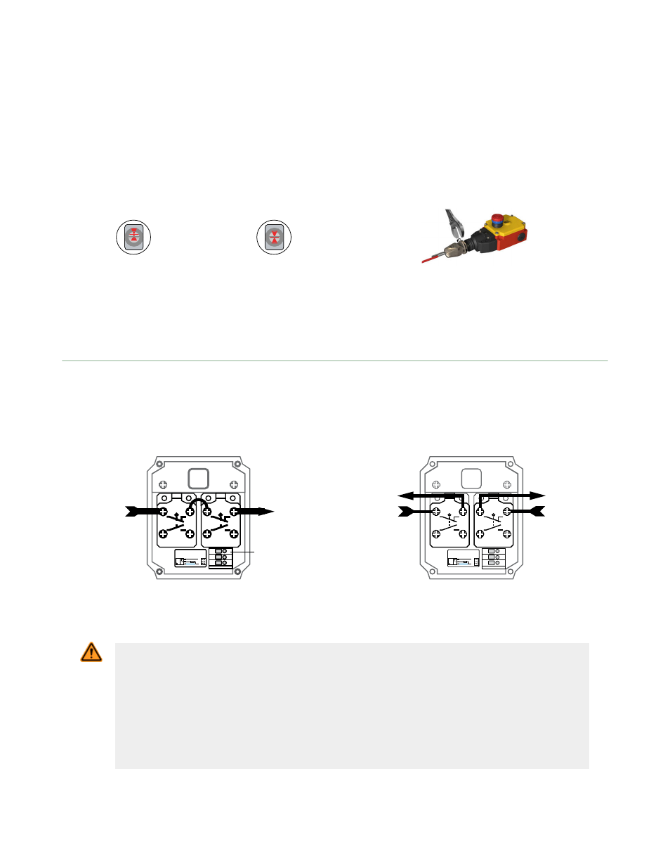
Tensioning the Rope
After the rope span components are installed, apply tension to the rope until the arrows in the tensioning indicator are
centered on the line in the tension indicator window. This indicates sufficient rope tension. (Contacts 11/12 will close.)
1. For models RP-RM83F-..LT and RP-RM83F-..LTE: Turn the external turnbuckle until the arrows are centered. For
models RP-RM83F-..LR and RP-RM83F-..LRE: Turn the shaft of the switch using a 17 mm wrench as shown, until
the arrows are centered.
2. Pull hard on the rope and reset the latch several times. If the arrows in the tensioning indicator window do not
return to the correct position (centered on the line in the window), further tighten or loosen the rope tension as
needed, then reset, until proper tension is shown.
3. Check the tension adjustment periodically to ensure proper operation.
Figure 6. Tension Indicator
Window: too little tension shown
Figure 7. Tension Indicator
Window: proper tension shown
Figure 8. Adjusting rope tension (models RP-RM83F-..LT
and-..LTE)
Electrical Installation
Accessing the Wiring Chamber
Access the wiring chamber by loosening the four corner screws to remove the front cover. Select the best wiring entrance
and thread in the ½" x 14 NPSM conduit adapter (supplied), or the optional M20 x 1.5 cable gland (see Accessories). Wire
the two switch contacts in series or independently.
11
12
23
24
11
12
23
24
–
+
1
2
3
1
2
3
Load
10-30 VDC
PNP
Warning Signal
Connections
Figure 9. Single-Channel Connection
11
12
23
24
11
12
23
24
–
+
1
2
3
1
2
3
Load
10-30 VDC
Channel A
Channel B
Figure 10. Dual-Channel Connection
WARNING: Shock Hazard and Hazardous Energy
Always disconnect power from the safety system (for example, device, module, interfacing,
etc.) and the machine being controlled before making any connections or replacing any
component.
Electrical installation and wiring must be made by Qualified Personnel and must comply with the
relevant electrical standards and wiring codes, such as the NEC (National Electrical Code), ANSI
NFPA79, or IEC 60204-1, and all applicable local standards and codes.
Lockout/tagout procedures may be required. Refer to OSHA 29CFR1910.147, ANSI Z244-1, ISO
14118, or the appropriate standard for controlling hazardous energy.
RP-RM83F Heavy-Duty Rope Pull Emergency Stop Switches
P/N 141245 Rev. C
www.bannerengineering.com - tel: 763-544-3164
5