Periodic checks, Repairs – Banner Compact Plastic Style Safety Interlock Switches User Manual
Page 6
Safety
Switch
#1
Safety
Switch
#2
Input
Channel
#1
Input
Channel
#2
2-channel Safety Module
(2-channel E-stop Module
2-channel Gate Monitor Module, etc.)
Single gate
or guard
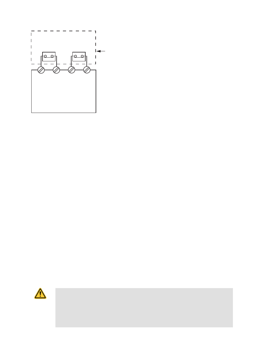
Figure 1. Connect two redundant safety switches per interlock
guard to an appropriate 2-channel input safety module.
Refer to the installation instructions provided with the safety mod-
ule for information regarding the interface of the safety module to
the machine stop control elements.
Periodic Checks
Safety switches should be checked at each shift change or machine setup by a designated person for:
1. Breakage of the switch body or actuator,
2. Good alignment and full engagement of the actuator with the receptor,
3. Confirmation that the safety switch is not being used as an end stop,
4. Loosening of the switch or actuator mounting hardware, and
5. Verification that it is not possible to reach any hazard point through an opened guard (or any opening) before hazardous machine
motion has completely stopped.
In addition, a qualified person should check for the following on a periodic schedule determined by the user based upon the severity of
the operating environment and the frequency of switch actuations:
1. Check the wiring chamber for signs of contamination.
2. Check the contacts for signs of deterioration or damage.
3. Inspect the electrical wiring for continuity and damage.
4. Verify the wiring conforms to the instructions given in this datasheet.
A designated person is identified in writing by the employer as being appropriately trained to perform a specified checkout procedure. A
qualified person possesses a recognized degree or certificate or has extensive knowledge, training, and experience to be able to solve
problems relating to the safety switch installation (ANSI B30.2).
Repairs
Do not attempt any repairs to the Module. It contains no field-replaceable components. Return it to the factory for warranty repair
or replacement by contacting Banner Factory Application Engineering. They will attempt to troubleshoot the system from your description
of the problem. If they conclude a component is defective, they will issue a return merchandise authorization (RMA) number for your
paperwork and give you the proper shipping address.
Pack the Module carefully. Damage that occurs in return shipping is not covered by warranty.
CAUTION: Abuse of Module After Failure
If an internal fault has occurred and the Module will not reset, do not tap, strike, or otherwise attempt to
correct the fault by a physical impact to the housing. An internal relay may have failed in such a man-
ner that its replacement is required.
If the Module is not immediately replaced or repaired, multiple simultaneous failures may accumu-
late such that the safety function can not be guaranteed.
Machine Safety Switches
6
www.bannerengineering.com - tel: 763-544-3164
P/N 049370 Rev. F