Mechanical installation – Banner Compact Plastic Style Safety Interlock Switches User Manual
Page 4
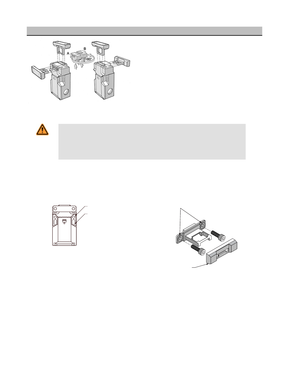
Rotating Actuator Head
The actuator head may be rotated 180° to create four possible ac-
tuator engagement locations. To rotate the head:
1. Open the wiring chamber door, as shown.
2. Using a small flat-blade screwdriver, dislodge the two locking
tabs located on the backside of the switch.
3. Lift the head straight off of the switch body.
4. Rotate the head, as shown, and reinstall it on the switch body.
Mechanical Installation
WARNING: Hazard Point
It must not be possible for personnel to reach any hazard point through an opened guard (or any
opening) before hazardous machine motion has completely stopped.
Please reference OSHA CFR 1910.217 and ANSI B11 standards for information on determining safety
distances and safe opening sizes for your guarding devices.
IMPORTANT: A safety switch must be installed in a manner that discourages tampering or defeat. Mount switches to prevent bypassing
of the switching function at the terminal chamber. A switch and its actuator must never be used as a mechanical stop. Overtravel may
cause damage to switch.
All mounting hardware is supplied by the user. The fasteners must be of sufficient strength to guard against incidental breakage. Use of
permanent fasteners or locking hardware is recommended to prevent loosening or displacement of the actuator and switch body.
Use ONLY for
alignment
during installation
Use for
permanent mounting
M5 (#10) Clearance
Snap-On Cap
1. Temporarily mount the switch body in place, with its actuator inserted, using the slotted 5 mm holes.
NOTE: The slotted holes in the switch body must ONLY be used for alignment during installation. The round 5 mm holes (only) must
be used for permanent mounting to prevent loosening or displacement of the actuator and the switch body. Only M5 (#10) screws
(user supplied), should be used.
2. Slide the switch body on its temporary fasteners to locate and mark the actuator mounting position. Remove the actuator from the
switch body and mount it using tamper-resistant 5 mm (#10) hardware (e.g., Torx-head screws, rivets, etc.). Slide the switch body on
its temporary fasteners to locate and mark the actuator mounting position. Remove the actuator from the switch body and mount it
using tamper-resistant 5 mm (#10) hardware (e.g., Torx-head screws, rivets, etc.).
NOTE: The non-adjustable in-line actuator includes floating sleeves in the mounting holes to allow some forgiveness for switch-to-
actuator alignment. Take care to not over-tighten the actuator fasteners so as to allow this movement. This actuator also includes a
snap-on cap to cover the fasteners.
Machine Safety Switches
4
www.bannerengineering.com - tel: 763-544-3164
P/N 049370 Rev. F