Magnetic switch models, Dimensions, Figure 10. dimensions figure 11. label – Banner ES-FA-6G Safety Module User Manual
Page 14
Inputs
Each switch or sensor must have a normally closed
contact and a normally open contact capable of switch-
ing 20 to 50 mA @ 15 to 30V dc.
Reset switch: 20 mA @ 12V dc, hard contact only
Max. external resistance between terminals S11/S12,
S11/S13, S21/S22 and S21/S23: 270 ohms each.Max.
external resistance between terminals S11/S12, S11/
S13, S21/S22 and S21/S23: 270 ohms each.
1-Channel operation: infinite
Environmental
Certifications
Vibration Resistance
10 to 55 Hz @ 0.35 mm displacement per IEC
60068-2-6
Operating Conditions
Temperature: 0° to +50°C (+32° to 122°F)
Maximum Relative Humidity: 90% @ +50°C (non-con-
densing)
Design Standards
CE: Cat. 4 PL e, per EN ISO 13849-1; SIL 3 per IEC
61508 and IEC 62061
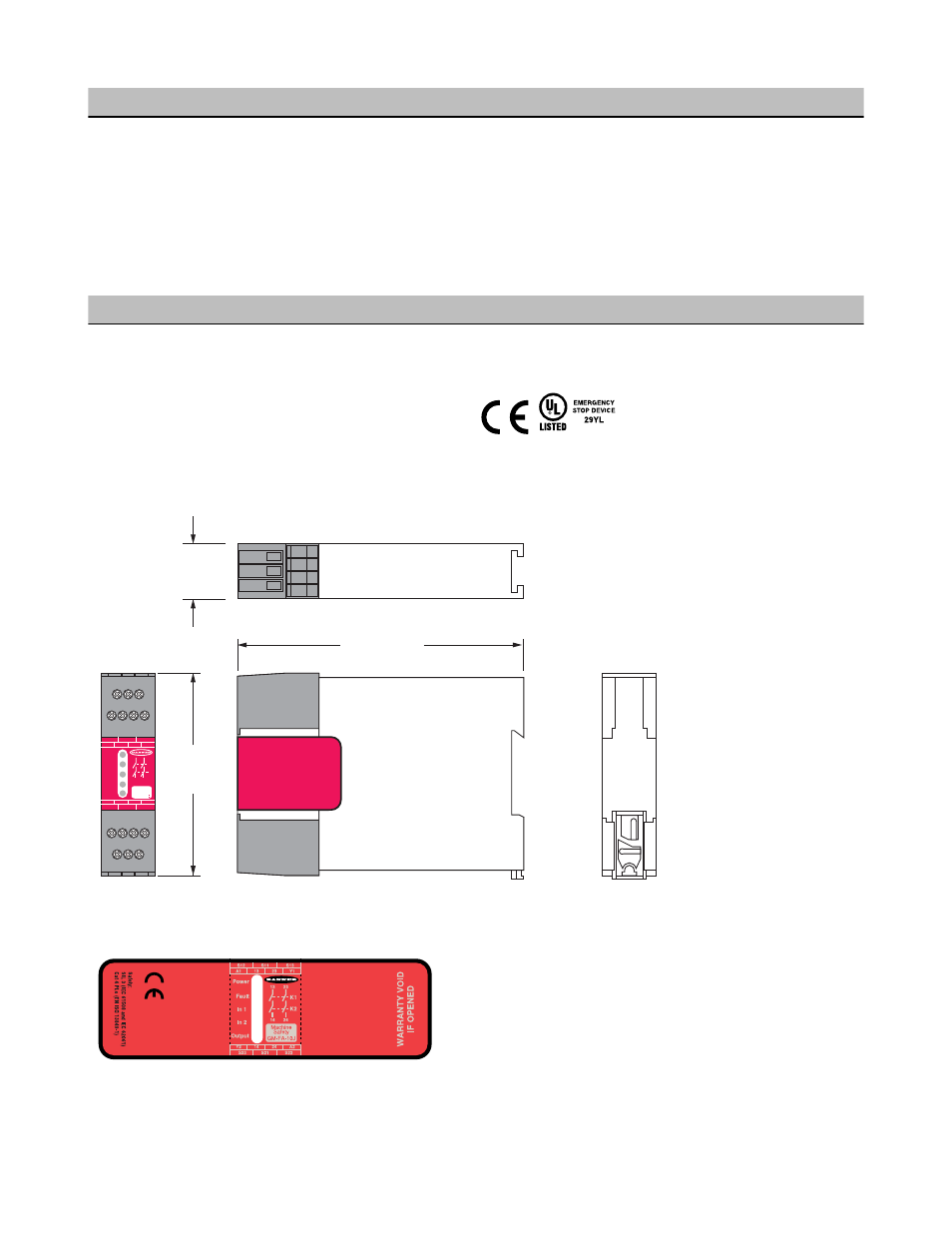
Dimensions
S12
A1
S11
S13
S23
S21
S22
13
23
Y1
Y2
14
24
A2
K1
K2
14 24
Machine
Safety
GM-FA-10I
Power
Fault
In 1
In 2
Output
118.0 mm
(4.65")
84.0 mm
(3.31")
22.5 mm
(0.89")
Figure 10. Dimensions
Figure 11. Label
Magnetic Switch Models
GM-FA-10J Gate Monitoring Safety Module
14
www.bannerengineering.com - tel: 763-544-3164
P/N 060998 Rev. F