Configuration – Banner ES-FA-6G Safety Module User Manual
Page 10
• A resistance or similar damping device capable of dissipating the energy of surges
When switching inductive ac loads, it is good practice to protect the Safety Module outputs by installing appropriately-sized arc suppres-
sors. However, if arc suppressors are used, they must be installed across the load being switched (e. g., across the coils of external
safety relays), and never across the Safety Module’s output contacts (see WARNING, Arc Suppressors).
Configuration
WARNING: Reset Routine Required
U.S. and international standards require that a reset routine be performed after clearing the cause of a
stop condition (for example, arming an E-stop button, closing an interlocked guard, etc.). Allowing the
machine to restart without actuating the normal start command/device can create an unsafe condi-
tion which could result in serious injury or death.
WARNING: Reset Switch Location
All reset switches must be accessible only from outside, and in full view of, the hazardous area.
Reset switches must also be out of reach from within the safeguarded space, and must be protec-
ted against unauthorized or inadvertent operation (for example, through the use of rings or guards). If
any areas are not visible from the reset switch(es), additional means of safeguarding must be provided.
Failure to do so could result in serious bodily injury or death.
Manual Reset and Reset Switch Connection
The reset switch must be capable of reliably switching 15 to 30V dc at 5 to 50 mA. As
shown in
Figure 7. Wiring to the guarded machine
on page 9, the reset switch connects
between terminals Y1 and Y2 of the Module. The reset switch must be located outside of –
and not accessible from – the area of dangerous motion, and it must be positioned so the
switch operator can see all areas of dangerous motion during the reset procedure (see
Warning).
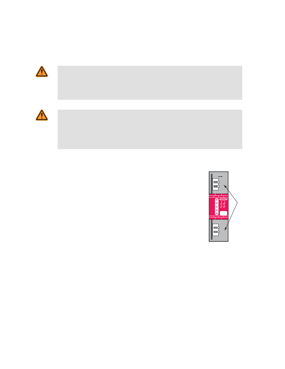
To configure the Module for Manual Reset, set switches S1.2 and S2.2 in banks A and B to
OFF. The reset switch may be any mechanical normally open switch, but should be a mo-
mentary switch or a two-position keyed switch. To reset the Module, both guards must be
closed, at which time the output LED will flash (signaling that the reset switch must be cy-
cled). This action is a monitored manual reset (open-closed-open), where the “closed”
phase is approximately 0.25 to 2 seconds long.
S21
A1
S11
S13
S23
S21
S22
13
23
Y1
Y2
14
24
A2
K1
K2
14 24
Machine
Safety
GM-FA-10J
Power
Fault
In 1
In 2
Output
DIP
Switch
Bank "A"
S1.1
S1.2
DIP
Switch
Bank "B"
S2.1
S2.2
S1.1/S2.1 OFF* – 2-Channel
ON – 1-Channel
S1.2/S2.2 OFF* – Manual Reset
ON – Auto Reset
* Factory Default
NOTE: Corresponding DIP switches
in Banks A and B must be set identically.
OFF
ON
Shown
with
terminal
blocks
removed
Figure 8. DIP switch configuration set-
tings for reset mode and 1- or 2-chan-
nel operation
Automatic Reset Mode
To configure the Module for Automatic Reset, set switches S1.2 and S2.2 in Banks A and B to ON. If no MPCE contacts are monitored,
install a jumper between terminals Y1 and Y2 (see
Figure 7. Wiring to the guarded machine
on page 9). The Safety Module will reset
(and its outputs will energize) as soon as the guards return to their closed position.
Automatic Reset is useful for some automated processes. However, if Automatic Reset is used, an alternate means must be provided to
prevent resumption of hazardous machine motion until an alternate reset procedure is performed. The alternate means must include a
GM-FA-10J Gate Monitoring Safety Module
10
www.bannerengineering.com - tel: 763-544-3164
P/N 060998 Rev. F