Configuration – Banner Safe Speed Monitoring Modules User Manual
Page 4
WARNING: WARNING . . . Wiring of Arc Suppressors. If arc suppressors are used, they MUST be installed as shown across
the coils of the Machine Primary Control Elements (MPCE1 to MPCE2). NEVER install suppressors directly across the output con-
tacts of the Safety Module. It is possible for suppressors to fail as a short circuit. If installed directly across the output contacts of the
Interface Module, a short-circuited suppressor will create an unsafe condition which could result in serious injury or death.
CAUTION: CAUTION . . . Shock Hazard. Always disconnect power from the Safety Module and all power from the machine
being controlled before making any wire connections. Electrical installation and wiring must be made by qualified personnel and
must comply with the NEC (National Electrical Code), EN60204-1 and -2, and all applicable local standards and codes.
External Device Monitoring. To satisfy the requirements of Control Reliability (OSHA and ANSI), Category 3 and 4 of ISO 13849-1 (EN 954-1), the Machine Primary
Control Elements (MPCEs) must each offer a normally closed, forced-guided (mechanically linked) monitor contact. Connect one normally closed monitor contact from each
Machine Primary Control Element as shown in the appropriate hookup drawing.
In operation, if one of the switching contacts of either MPCE fails in the energized condition, the associated monitor contact will remain open. Therefore, it will not be
possible to reset the Primary Safety Device. If no MPCE-monitor contacts are monitored, it is the user's responsibility to ensure that any single failure will not result in a
hazardous condition and will prevent a successive machine cycle.
Overvoltage Category II and III Installations (EN 50178 and IEC 60664-1). The Safety Module is rated for Overvoltage Category III when voltages of 1V to 150V ac/dc
are applied to the output relay contacts. It is rated for Overvoltage Category II when voltages of 151V to 250V ac/dc are applied to the output relay contacts and no
additional precautions are taken to attenuate possible overvoltage situations in the supply voltage. The Module can be used in an Overvoltage Category III environment
(with voltages of 151V to 250V ac/dc) if care is taken either to reduce the level of electrical disturbances seen by the Module to Overvoltage Category II levels by installing
surge suppressor devices (e.g., arc suppressors), or to install extra external insulation in order to isolate both the Safety Module and the user from the higher voltage levels
of a Category III environment.
For Overvoltage Category III installations with output contact voltage 151V to 250V ac/dc applied to the output contact(s): the Safety Module may be used under
the conditions of a higher overvoltage category where appropriate overvoltage reduction is provided. Appropriate methods include:
• An overvoltage protective device
• A transformer with isolated windings
• A distribution system with a multiplicity of branch circuits (capable of diverting energy of surges)
• A capacitance capable of absorbing energy of surges
• A resistance or similar damping device capable of dissipating the energy of surges
When switching inductive ac loads, it is good practice to install appropriately-sized arc suppressors to protect the Safety Module outputs. However, if arc suppressors are
used, they must be installed across the load being switched (e. g., across the coils of external safety relays), and never across the Safety Module's output contacts (see
WARNING, "Wiring of Arc Suppressors").
Auxiliary Monitor Contact. The action of the auxiliary monitor contact, terminals 31-32, inversely "follows" the action of the safety outputs. The 31-32 auxiliary monitor
contact is to be used only for control functions that are NOT safety-related. A typical use is to communicate the status of the Safety Module output to a programmable logic
controller (PLC).
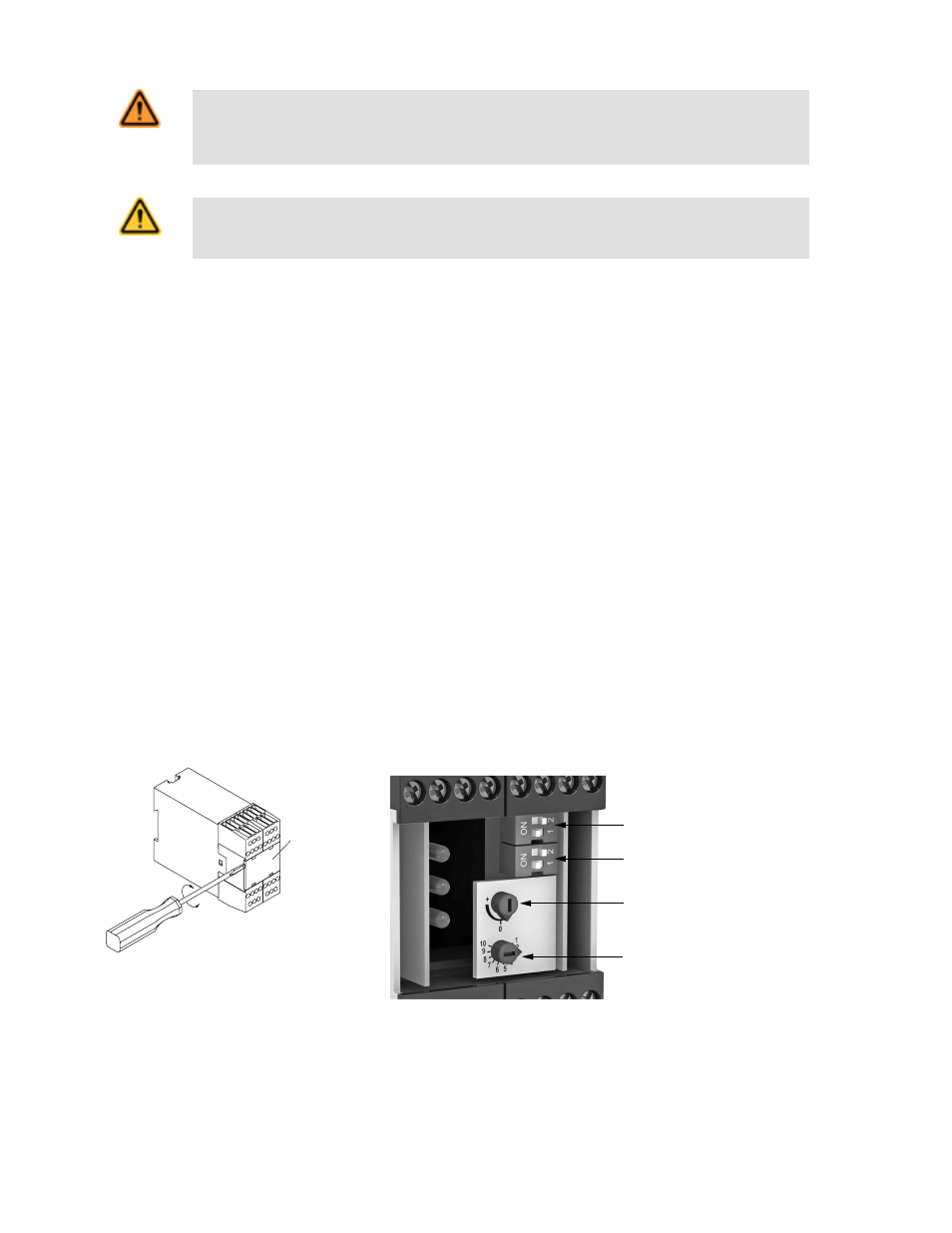
Configuration
Front
plate
Figure 5. Removing the front cover
1
2
3
4
Figure 6. Module adjustments
1. DIP switch bank A
2. DIP switch bank B
3. Simultaneity adjustment potentiome-
ter
4. Fine-tune potentiometer
Use DIP switch banks A and B together to set the ranges. For example, to select the first range setting, set DIP switch 1 in bank A and in bank B to OFF, set DIP switch 2 in
bank A and bank B to OFF.
SSM-FM-11A... Safe Speed Monitoring Modules
4
www.bannerengineering.com - tel: 763-544-3164
P/N 140782 rev. C