Banner Safe Speed Monitoring Modules User Manual
Page 3
Reset and Startup Conditions. The Module works only in automatic reset mode. In order for
the Module to switch to RUN mode for normal operation, the Y1 - Y2 feedback input must be
closed during power-up.
The Module typically requires two to three seconds after power ON to evaluate the signals
from the two sensors and to decide if the number of incoming signals/pulses is above or be-
low the set switch point value. After three seconds, if the Module detects a number of pulses
per minute below the set value, the relays energize and the output contacts turn ON, indicat-
ing a standstill condition. If the machine being monitored and the Module are powered up at
the same time, the machine has only three seconds to come up to speed, or the Module de-
tects a standstill condition. If the machine requires more than three seconds, power up the
machine first, then the Module, after the appropriate delay.
When each of the internal relays is energized, its corresponding LED turns ON green. Both
relay outputs activate only if both inputs reach the enabling conditions within approximately
two seconds. If the signals are not received within two seconds (e.g., because of a defective
sensor or because the channels did not switch simultaneously), the output contacts will not
turn ON, and power to the Module must be cycled.
SSM-FM-11A10
or
SSM-FM-11A20
Sensor 2
24V ac/dc
0 V
K1
A
4 A max.
K2
A
K1
B
K2
B
K1
C
K2
C
Y1
MSC1
MSC
Monitor
Contacts
or Jumper
MSC2
+24V
0V
PNP
Signal
Out
13
S2+
S2s
S2-
Sensor 1
+24V
0V
PNP
Signal
Out
S1+
A2
A1
S1s
S1-
14
24
31
32
Y2
23
See External Device
Monitoring
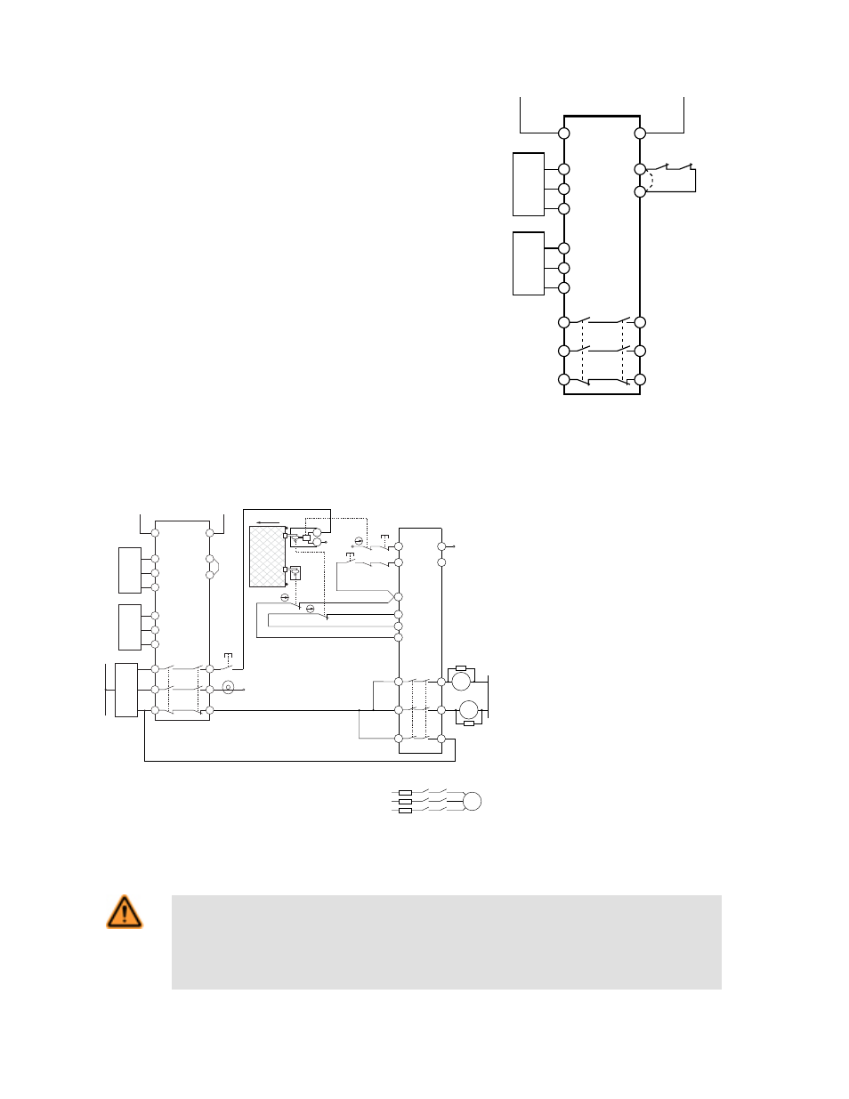
Figure 3. Typical hookup to two sensors
Connection to the Machine to be Controlled. The machine hookup diagram shows a generic connection of the Safety Module's redundant output circuits to the Machine
Primary Control Elements MPCE1 and MPCE2. A Machine Primary Control Element is an electrically powered device, external to the Interface Module, which stops the
machinery being controlled by immediately removing electrical power from the machine and (when necessary) by applying braking to dangerous motion.
0V
0V
n.c.
K1
A
K2
A
K1
B
K2
B
K1
C
K2
C
13
14
23
24
33
34
ES-FA-9AA
SSM-FM-11A10
or
SSM-FM-11A20
Sensor 2
24V ac/dc
0V
K1
A
4A max.
K2
A
K1
B
K2
B
K1
C
K2
C
Machine
Control
Circuits
Y1
Unlock (3)
OK to Open
+24V
0V
PNP
Signal
Out
13
S2+
S2s
S2-
Sensor 1
+24V
0V
PNP
Signal
Out
S1+
A2
A1
S1s
S1-
14
24
31
32
Y2
23
S12
S22
S21
24V ac/dc
Start
Function
(7)
A2
S34
OPEN
E1
E2
0V
0V
(5)
MPCE
1
MPCE
2
A1
S33
24V
ac/dc
(6)
MPCE1 MPCE2
Request to
Enter (2)
S11
Reset
(1)
M
MPCE1 MPCE2
(5)
(4)
Figure 4. Machine connection with an interlocked guard with guard locking and another safety mod-
ule
(1) Safety Module ES-FA-9AA is configured for manual re-
set. See data sheet p/n 60606 for complete information.
Other Safety Modules can be used. Call Banner Engineer-
ing with all questions.
(2) After the guard has been closed, the Safety Module has
been reset, and the machine control has started the motor,
the Request to Enter button can be pushed to interrupt the
cycle.
(3) The machine control and the SSM Safe-Speed Monitor-
ing Module enable the Unlock button and illuminate the OK
to Open light.
(4) The signal from the Unlock button energizes the sole-
noid locking mechanism of the locking style safety switch,
allowing the guard to be opened. It is recommended to lo-
cate the Unlock button near the associated guard. The sole-
noid contact prevents the reset of the ES-FA-9AA Safety
Module until the guard is locked.
(5) Arc Suppressor, see Warning.
(6) See the External Device Monitoring section and the
warning, Interfacing MPCEs.
(7) Not all feedback or monitoring functions of the machine
interface are shown.
WARNING: WARNING . . . Interfacing MPCEs. NEVER wire any intermediate device(s) (e.g., PLC, PES, PC), between the
Safety Module outputs and the Machine Primary Control Elements (MPCE1 to MPCE3) it switches, in such a manner that in
the event of a failure there is the loss of the safety stop command, OR in such a manner that the safety function can be
suspended, overridden, or defeated, unless accomplished with the same or greater degree of safety. Whenever forced-gui-
ded, mechanically linked relays are added as intermediate switching devices, a normally closed forced-guided monitor contact from
each relay must be added to the series feedback loop between Interface Module terminals Y1 and Y2.
SSM-FM-11A... Safe Speed Monitoring Modules
P/N 140782 rev. C
www.bannerengineering.com - tel: 763-544-3164
3