Operation and requirements, Mechanical installation, Electrical installation – Banner Safe Speed Monitoring Modules User Manual
Page 2
Operation and Requirements
The Module is redundant and self-checking. It requires digital input signals from two independent input sensors (e.g., proximity switches) to monitor for either standstill
(under-speed) or over-speed conditions.
The input channels are factory pre-adjusted for simultaneity, and a simultaneity potentiometer (behind the Module front cover) is available to further synchronize the input
channel timing. Two banks of DIP switches are also located behind the front cover, for the purpose of selecting the switch point range; a second potentiometer is used to
fine-tune the switch point setting. See Figure, "Module adjustments."
Input Sensor Requirements. Both sensors must have 24V PNP outputs. Because the
Module continually monitors its connections to each sensor, each sensor must draw a min-
imum current of 3 mA at all times (in either the OFF or ON state). The Module will detect if
any of the three wires from the sensor to the Module are interrupted. A broken sensor wire
will always result in an OFF condition.
• If the safety outputs are ON when a sensor wire breaks or is disconnected, the related
internal relay turns OFF and the safety outputs open, signaling "No Standstill" and/or
"Over-speed."
• If the safety outputs are OFF when a sensor wire breaks or is disconnected, they can
not turn ON (again signaling "No Standstill" and/or "Over-speed") until the sensor con-
nection is fixed.
Sensor Mounting Requirements: For safe and reliable operation, the two input sensors
must be mounted so that they are vibration-free, their signals are received simultaneously,
and they don't influence each other.
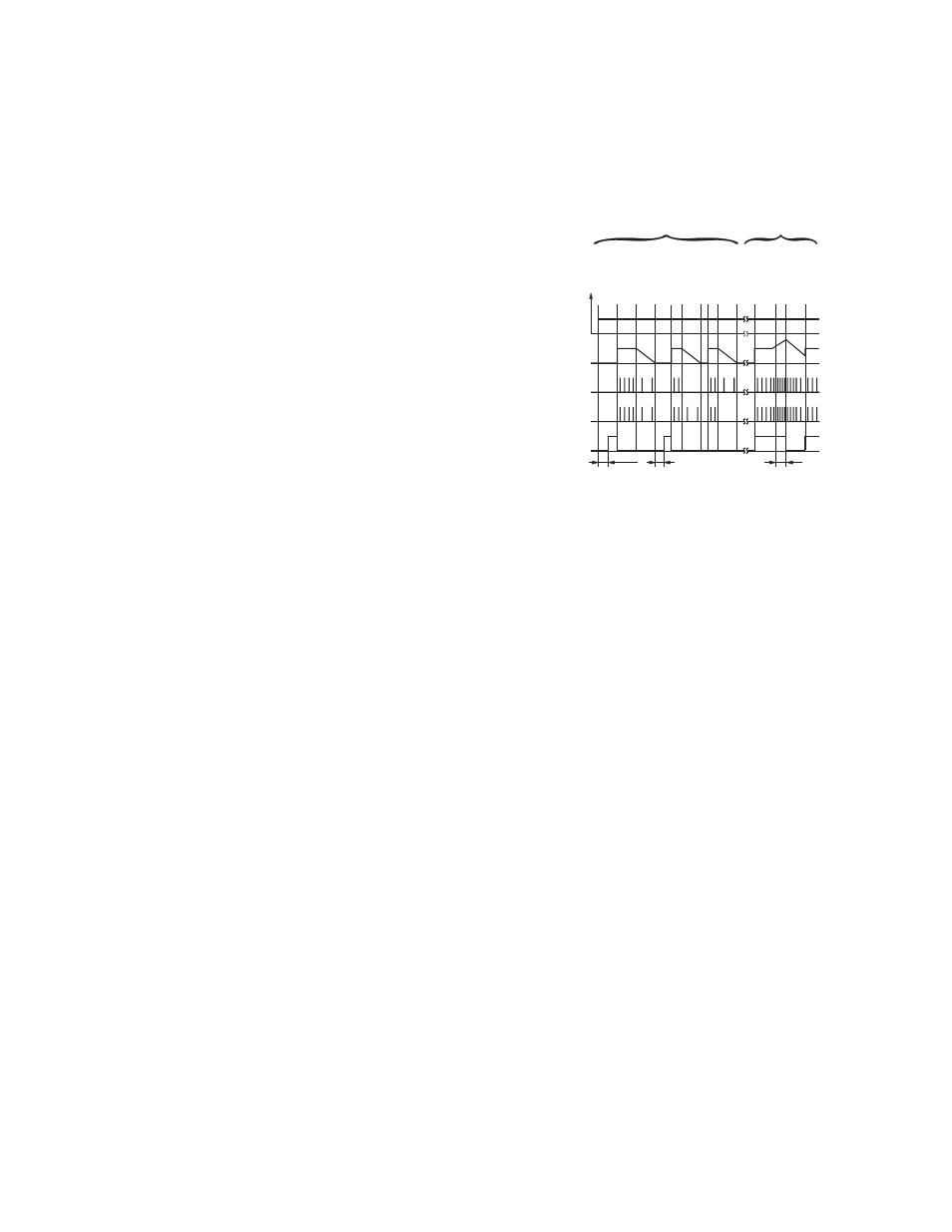
t
tds
Res +
Res
tds
tdo
13-14
23-24
Stop
Stop
Stop
Motor Standstill
Motor ON
Supply
ON
Standstill
Detection
Overspeed Detection
Motor ON
Overspeed
S1s
0V
A1/A2 +24V
S1s: Output signal from sensor A
Motor
Speed
S2s
Motor Standstill
Motor Standstill
Motor ON
Motor ON
Motor OFF
Motor ON
S2s: Output signal from sensor B
t : Power-up delay
detection
t : Response after overspeed detection
do
ds
t : Response after standstill/underspeed
Figure 2. Functional Diagram
Mechanical Installation
The Safety Module must be installed inside an enclosure.
It is not designed for exposed wiring. It is the user’s responsibility to house the Safety Module in an enclosure with NEMA 3 (IEC IP54) rating, or better. The Safety Module
mounts directly to standard 35 mm DIN rail.
Heat Dissipation Considerations. For reliable operation, ensure that the operating specifications are not exceeded. The enclosure must provide adequate heat dissipa-
tion, so that the air closely surrounding the Module does not exceed the maximum operating temperature stated in the Specifications. Methods to reduce heat build-up
include venting, forced airflow (e.g., exhaust fans), adequate enclosure exterior surface area, and spacing between modules and other sources of heat.
Electrical Installation
It is not possible to give exact wiring instructions for a Safety Module which interfaces to a multitude of machine control configurations. The following guidelines are general
in nature.
The Safety Module has no delay function. Its output relay contacts open within the time frame determined by the formula shown in the Configuration section. This classifies
the Safety Module as functional stop "Category 0", as defined by ANSI NFPA 79 and IEC/EN 60204-1.
Input Sensor Connections. The Module provides 24V dc and 0V to power the sensors through S1+/S1- and S2+/S2-. The sensor output signals are connected to termi-
nals S1s and S2s.
SSM-FM-11A... Safe Speed Monitoring Modules
2
www.bannerengineering.com - tel: 763-544-3164
P/N 140782 rev. C