Installation instructions – Brandmotion 1008-6502 User Manual
Page 7
INSTALLATION INSTRUCTIONS
6501 and 6502 Instructions 6-13-12.doc
7 of 20
Section 4: Wiring for Aftermarket Display
22. If needed, install aftermarket display or
navigation display per instructions.
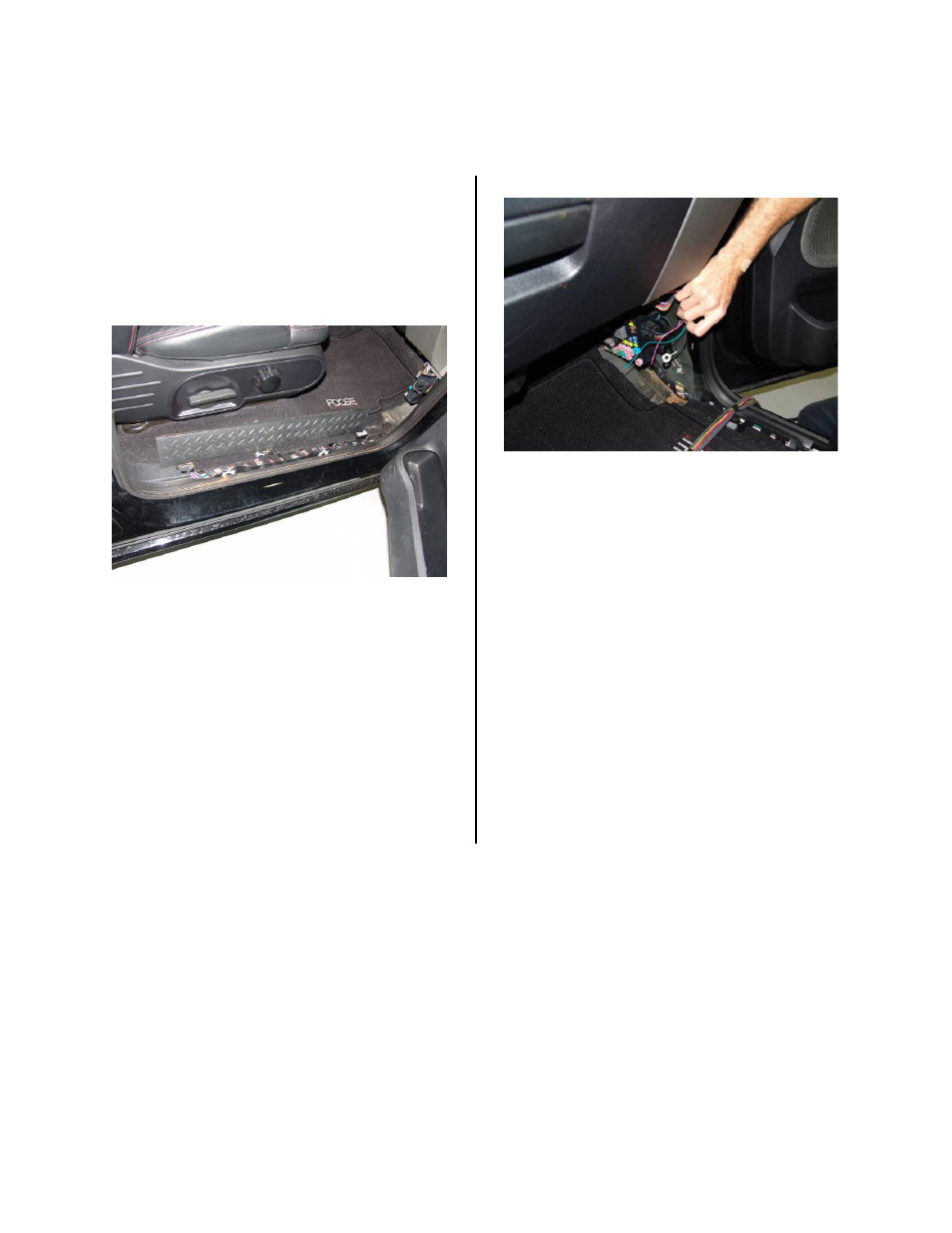
23. Remove the passenger side door sill plate
with a trim tool and remove passenger side
kick panel with hands, just disengaging the
two clips from the sheet metal (Figure 23).
Figure 23
24. Route the supplied chassis harness green,
red, and black wires along the vehicle cross
dash harness as shown. Secure using wire
ties wherever possible at 2 inch intervals.
25. Splice the green reverse wire from the
supplied chassis harness to the wire listed
in Diagram A, on page 8. Solder and cover
the connection with tape or heat shrink
tubing.
26. Attach the black ground wire eyelet from
the supplied chassis harness to sheet metal
in the passenger side kick panel with a
screw using an 8mm socket (Figure 24).
Figure 24
27. Splice the red ignition wire from the
supplied chassis harness to the wire listed
in Diagram A, on page 8. Solder and cover
the connection with tape or heat shrink
tubing.
28. Connect the male RCA from the chassis
harness to the camera IN on the
aftermarket display or navigation display. In
some cases a RCA extension may be
required.
29. Start the vehicle and shift into reverse. If all
of the connections are correct an image will
appear on the aftermarket display or
navigation display.
30. Reinstall all previously removed interior and
exterior parts.