Installation instructions – Brandmotion 1008-6509-V2 User Manual
Page 7
INSTALLATION INSTRUCTIONS
6509 Instructions 5-22-12 Flex.doc
7 of 9
Section 4: Ignition, Reverse and Ground Locations
37. If needed, install aftermarket display or
navigation display per instructions.
38. Remove driver side kick panel.
39. Splice the green reverse wire from the
supplied chassis harness to the wire listed in
Connector C925 diagram on page 8. Solder
and cover the connection with tape or heat
shrink tubing.
40. Attach the black ground wire eyelet
from the supplied chassis harness to sheet
metal with an existing screw using an 8mm
socket (Figure 15).
Figure 15
41. Splice the red ignition wire from the
supplied chassis harness to the wire listed in
Connector C925 diagram on page 8. Solder
and cover the connection with tape or heat
shrink tubing.
42. Connect the male RCA from the chassis
harness to the camera IN on the aftermarket
display or navigation display. In some cases a
RCA extension may be required.
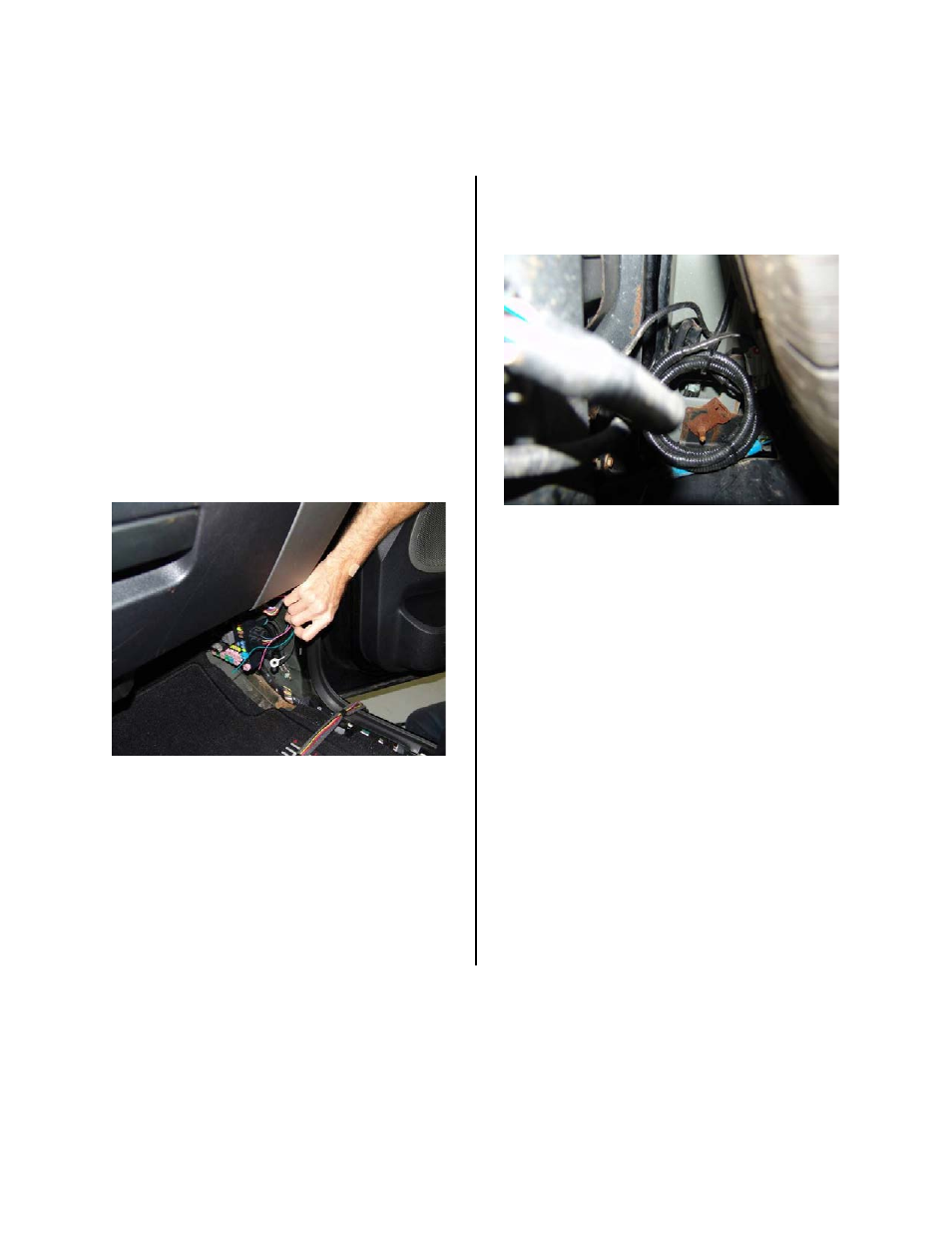
43. Coil and secure any excess chassis
harness with remaining wire ties (Figure 16)
Figure 16
44. Start the vehicle and shift into reverse.
If all of the connections are correct an image
will appear on the aftermarket display or
navigation display.
45. Reinstall all previously removed interior
and exterior parts.
46. Press the supplied emblem into the
liftgate camera mount.