Installation instructions – Brandmotion 9002-8837 User Manual
Page 5
INSTALLATION INSTRUCTIONS
8837 Instructions 10-7-14.docx
Page 5 of 6
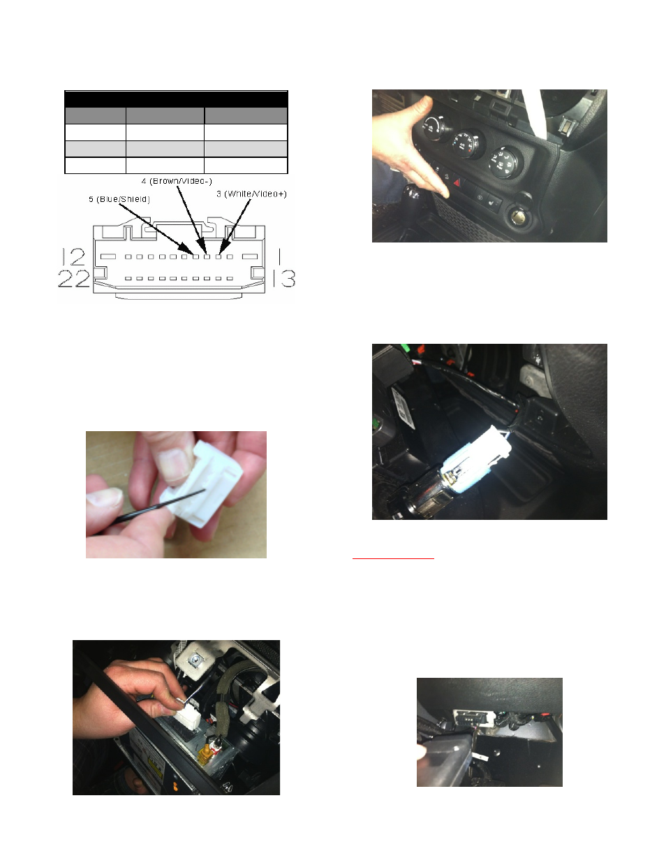
Step 30: Pin out supplied White 22-pin Connector as
indicated:
22-Pin Connector Pinout
CAVITY # WIRE COLOR
FUNCTION
3
White
Video (+)
4
Brown
Video (–)
5
Blue
Shield
Insert the white, brown and blue terminals of the
interior harness into the supplied white Radio Head Unit
22-pin connector, as indicated in the above, until they
click into place. Note: If the terminals do not click into
place, you must disengage Terminal Position Assurance
(TPA) device (the large rectangular bar) on the
connector. Pry up on the notches in the TPA with a small
watch repair screwdriver. The tab will only lift about
1/10
”
.
Press down on the TPA device to lock the wires into the
22-pin connector. NOTE: The TPA will not lock flush if
terminal(s) are not seated completely.
Step 31: Insert the white 22-pin connector into the
back of radio.
Step 32: Using a plastic trim removal tool, remove
HVAC panel.
Step 33: Run Red 12v+ ignition wire of supplied
Interior Harness to ignition controlled power point on
HVAC panel power point.
Step 34: Splice Red power wire to Blue/Red wire on
back of power point. RECOMMENDED: Use solder and
cover with heat shrink tubing or use T-taps as an
alternate connection method.
Programing Instructions
PLEASE NOTE: These modules are VIN locked for
single use.
a) With the module not plugged in, key on the
ignition and wait 10 seconds for the chimes and
lights to stop flashing.
b) Plug module into OBDII port, located under the
dash on the driver’s side, and wait to hear “honk
honk”. Programming is completed.
c) Unplug the module from the OBDII port.