Operating instructions, Installation instructions, Pinout reference chart – Brandmotion 9002-8521 User Manual
Page 5
INSTALLATION INSTRUCTIONS
8521 Instructions 7-26-13.doc
Page 5 of 5
Step 23: Route Chassis Harness forward. It may
be necessary to remove sill plates, pillar covers,
seat bottoms, side panels, etc. In some cases even
the seatbelt bolts at the bottom of the pillars must
be removed.
CAUTION: Any bolts removed for safety devices
must be retightened to manufacturer’s specified
torque specifications). Use a Plastic Trim
Removal Tool to avoid damage to trim pieces.
Step 24: Secure Camera Harness to existing
vehicle wiring using supplied Wire Ties. This will
minimize chance of binding or otherwise damaging
the harness
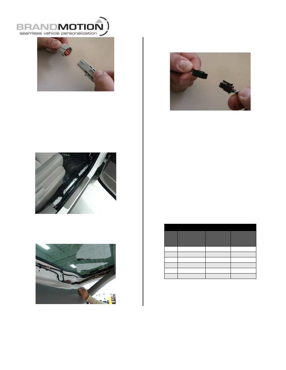
Step 25: Connect Chassis Harness to supplied
Mirror Harness.
Step 26: Test the system. Inspect that all
connections are proper and secure. Clear all loose
items removed from the area around the vehicle
and turn ignition key ON to test system. Once
Reverse gear is engaged the camera image should
appear on the mirror.
Step 27: Secure Chassis Harness and Mirror
Harness with supplied Zip Ties. If necessary, coil
excess harness wire and secure with Zip Ties.
Attach to existing vehicle wiring where possible.
Step 28: Adjust camera aim. With the aid of an
assistant, move camera to desired view, and
tighten the Bolts that hold the camera in place.
Step 29: Reassemble vehicle. Follow your
disassembly steps in reverse order, taking care not
to bind the harness wiring when reinstalling.
Pinout Reference Chart
PIN
#
FUNCTION
CAMERA
HARNESS
COLOR
CHASSIS
HARNESS
COLOR
1
Video (+)
Yellow
White
2
Shield
White
Blue
3
Reverse
Blue
Green
4
Video (–)
Brown
Brown
5
Ground
Black
Black
6
Ignition
Red
Red
OPERATING INSTRUCTIONS
Temporary Monitor Manual Shut Down. If while in Reverse you require to turn OFF the camera
monitor, simply press and release the POWER button on the mirror. (Note: once Reverse is disengaged
the mirror will go back to normal operation and will turn ON next time Reverse is engaged).