Installation instructions, Mirror harness connection chart – Brandmotion 9002-8521 User Manual
Page 4
INSTALLATION INSTRUCTIONS
8521 Instructions 7-26-13.doc
Page 4 of 5
Step 17: Follow the appropriate supplied charts to
splice the Orange & White leads to wires in your
existing vehicle mirror harness:
Wire
Color
Ford Mirror Connector
7 Pin
10 Pin
16 Pin
Function
Orange Cavity 4
Cavity 8 Cavity 11 Mirror Feed +
White
Cavity 5
Cavity 7 Cavity 15 Mirror Feed –
Wire
Color
Dodge Mirror Connector
16 Pin
Function
Orange
Cavity 11
Mirror Feed +
White
Cavity 15
Mirror Feed –
For vehicles not listed, use a Digital Multimeter
to identify the wires in the existing vehicle mirror
harness that feed the Exterior Auto-Dimming
Mirrors. Splice supplied Orange lead to Auto-
Dimming (+) and White lead to Auto-Dimming (–).
Step 18: Plug the black 16-pin connector into the
rear of the mirror.
Step 19: Route supplied Mirror Harness under the
headliner and down the A-pillar nearest vehicle
power and reverse signal.
Step 20: Splice the red and green Mirror Harness
leads into the corresponding vehicle wires and the
black wire to chassis ground. (Note: Soldering
recommended or use supplied T-taps as optional
connection method). RECOMMENDED: Attach an
eyelet to the black ground wire.
Red - Ignition controlled power 12v+ when key
is turned ON and 14.4v or better when
vehicle is running.
Black - Chassis ground.
Green - Connect to Reverse + signal (backup
lamp).
Note: If installing in a Ford vehicle with a separate
compass display on the instrument panel and
it displays “– –“ after the OE mirror is
removed, you must follow online steps in
Section 6 of 1008-9520 instructions posted at
www.Brandmotion.com in order for it to
function again.
Mirror Harness Connection Chart
Wire
Color
Polarity Function
Description
Location
note
Red
12v +
Ignition
controlled
power
This lead
displays 12
volt + when
the key is in
the RUN
position
Commonly
found on
main
Ignition
harness.
Black
(–)
Ground
Chassis
ground
A ground
bolt is
commonly
found in the
front kick
panel area.
Green
12v +
Reverse
trigger
(Backup
Lights)
This lead is
activated
when the
vehicle is
engaged into
Reverse
Commonly
found in
front kick
panel area
on harness
coming
from rear of
vehicle.*
*If Reverse cannot be located, connect the both the Red and Green
wires to Ignition power.
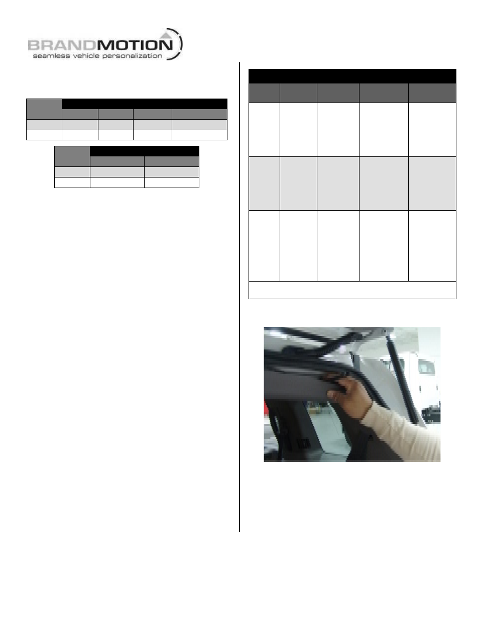
Step 21: Route Camera Harness towards the side
of the vehicle that supplies power.
Step 22: Connect Camera Harness to supplied
Chassis Harness. The optimal location for this
junction may occur at the top of the liftgate or the
inner edge of the trunk. (Note: Most vehicles have
existing wires passing through this area; use this
route if at all possible).