Figure 4 dps element orientation, Connecting the wideband power sensor (wps), Connecting the terminating power sensor (tps) – Bird Technologies 5000-XT-Manual User Manual
Page 23
9
For Models 5014:
Connect the Bird DPS to the “Sensor” USB port on the DPM using the
sensor cable provided.
2.
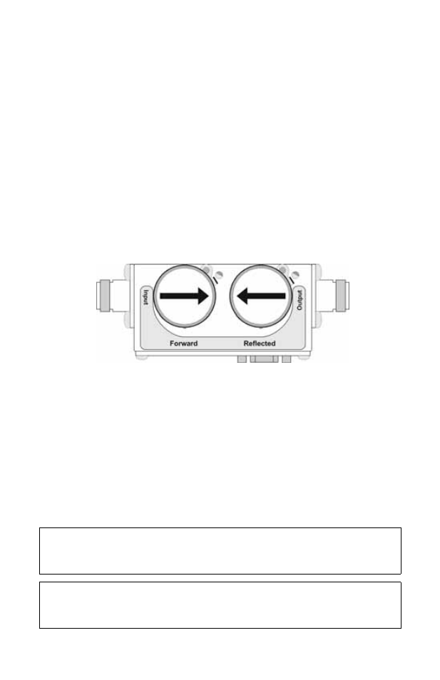
Connect the DPS to the RF line so that the arrow on the sensor points
towards the load.
Note: The arrow on the forward element should point towards the
load.
Note: The arrow on the reflected element should point towards the
source.
Note: Both elements must be either APM/DPM or 43 types, do not
mix elements.
3.
Set the power on the DPM to the forward element’s power rating.
Figure 4 DPS Element Orientation
Connecting the Wideband Power Sensor (WPS)
1.
Do one of the following:
Connect the DPM port on the Bird WPS to the “Sensor” serial port on
the DPM using the sensor cable provided.
Connect the DPM port on the Bird WPS to the “Sensor” USB port on the
DPM using the sensor cable provided.
2.
Connect the WPS to the RF line so that the arrow on the sensor points
towards the load.
Connecting the Terminating Power Sensor (TPS)
CAUTION
Discharge all static potentials before connecting the TPS(-EF). Electrostatic
shock could damage the sensor.
CAUTION
When connecting the TPS or the TPS-EF, only turn the connector nut. Damage
may occur if torque is applied to the sensor body.