Appendix iv. electrical data (cont.), Mca/mocp determination no c.o. or unpwrd c.o – Bryant 580J*04--12 User Manual
Page 69
69
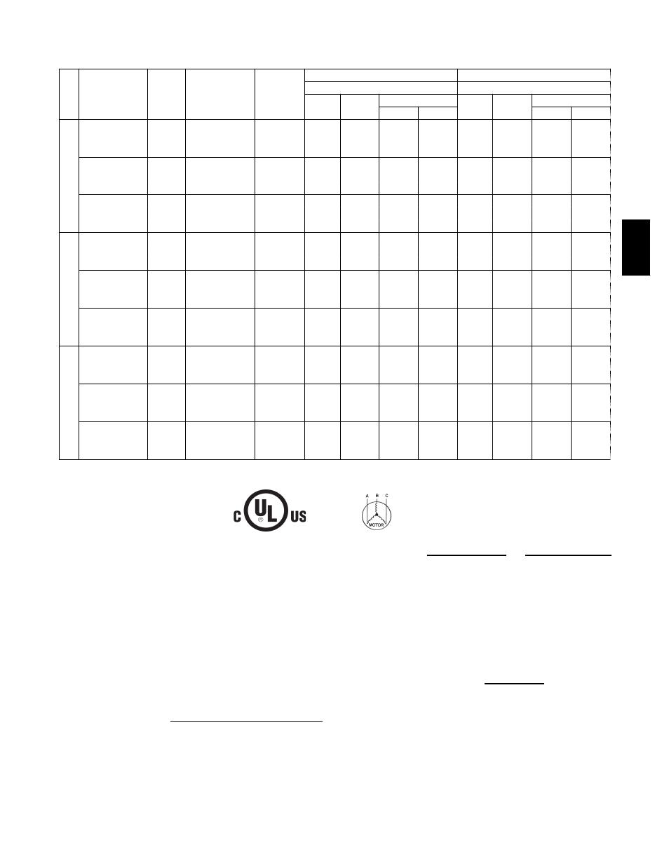
APPENDIX IV. ELECTRICAL DATA (cont.)
MCA/MOCP DETERMINATION NO C.O. OR UNPWRD C.O.
UN
IT
NOM.
V---Ph---Hz
IFM
TYPE
COMBUSTION
FAN MOTOR
FLA
POWER
EXHAUST
FLA
NO C.O. or UNPWRD C.O.
NO C.O. or UNPWRD C.O.
NO P.E.
w/ P.E. (pwrd fr/ unit)
MCA
MOCP
DISC. SIZE
MCA
MOCP
DISC. SIZE
FLA
LRA
FLA
LRA
580J
*0
8
208/230---3---60
STD
0.48
3.8
39.5
60
38
191
43.3
60
43
195
MED
41.8
60
41
228
45.6
60
45
232
HIGH
49.3
60
49
254
53.1
60
54
258
460---3---60
STD
0.25
1.8
19.5
30
19
113
21.3
30
21
115
MED
20.3
30
20
132
22.1
30
22
134
HIGH
24.3
30
24
145
26.1
30
26
147
575---3---60
STD
0.24
3.8
14.9
20
14
89
18.7
25
19
93
MED
15.3
20
15
104
19.1
25
19
108
HIGH
18.1
25
18
118
21.9
30
23
122
580J
*0
9
208/230---3---60
STD
0.48
3.8
45.1
60
43
222
48.9
60
48
226
MED
45.1
60
43
233
48.9
60
48
237
HIGH
49.9
60
49
276
53.7
80
53
280
460---3---60
STD
0.25
1.8
22.6
30
22
108
24.4
30
24
110
MED
22.6
30
22
114
24.4
30
24
116
HIGH
24.4
30
24
136
26.2
30
26
138
575---3---60
STD
0.24
3.8
18.9
30
18
91
22.7
30
23
95
MED
18.5
30
18
95
22.3
30
22
99
HIGH
19.3
30
19
106
23.1
30
23
110
580J
*1
2
208/230---3---60
STD
0.48
3.8
45.8
60
44
263
49.6
60
48
267
MED
50.6
60
50
306
54.4
80
54
310
HIGH
55.6
80
55
315
59.4
80
60
319
460---3---60
STD
0.25
1.8
25.1
30
24
133
26.9
40
26
135
MED
26.9
40
26
155
28.7
45
28
157
HIGH
29.9
45
30
159
31.7
45
32
161
575---3---60
STD
0.24
3.8
18.5
30
18
95
22.3
30
22
99
MED
19.3
30
19
106
23.1
30
23
110
HIGH
22.1
30
22
120
25.9
30
26
124
1
Fuse or breaker
LEGEND:
CO
--- Convenient outlet
DISC
--- Disconnect
FLA
--- Full load amps
IFM
--- Indoor fan motor
LRA
--- Locked rotor amps
MCA
--- Minimum circuit amps
MOCP
--- Maximum over current protection
PE
--- Power exhaust
UNPWRD CO --- Unpowered convenient outlet
NOTES:
1. In compliance with NEC requirements for multimotor and
combination load equipment (refer to NEC Articles 430 and
440), the overcurrent protective device for the unit shall be
fuse or HACR breaker. Canadian units may be fuse or circuit
breaker.
2.
Unbalanced 3-Phase Supply Voltage
Never operate a motor where a phase imbalance in supply
voltage is greater than 2%. Use the following formula to de-
termine the percentage of voltage imbalance.
% Voltage Imbalance
= 100 x
max voltage deviation from average voltage
average voltage
Example: Supply voltage is 230-3-60
AB = 224 v
BC = 231 v
AC = 226 v
Average Voltage =
(224 + 231 + 226)
=
681
3
3
=
227
Determine maximum deviation from average voltage.
(AB) 227 – 224 = 3 v
(BC) 231 – 227 = 4 v
(AC) 227 – 226 = 1 v
Maximum deviation is 4 v.
Determine percent of voltage imbalance.
% Voltage Imbalance
= 100 x
4
227
= 1.76%
This amount of phase imbalance is satisfactory as it is below the
maximum allowable 2%.
IMPORTANT: If the supply voltage phase imbalance is more than
2%, contact your local electric utility company immediately.
580J