Red led-status – Bryant 580J*04--12 User Manual
Page 29
29
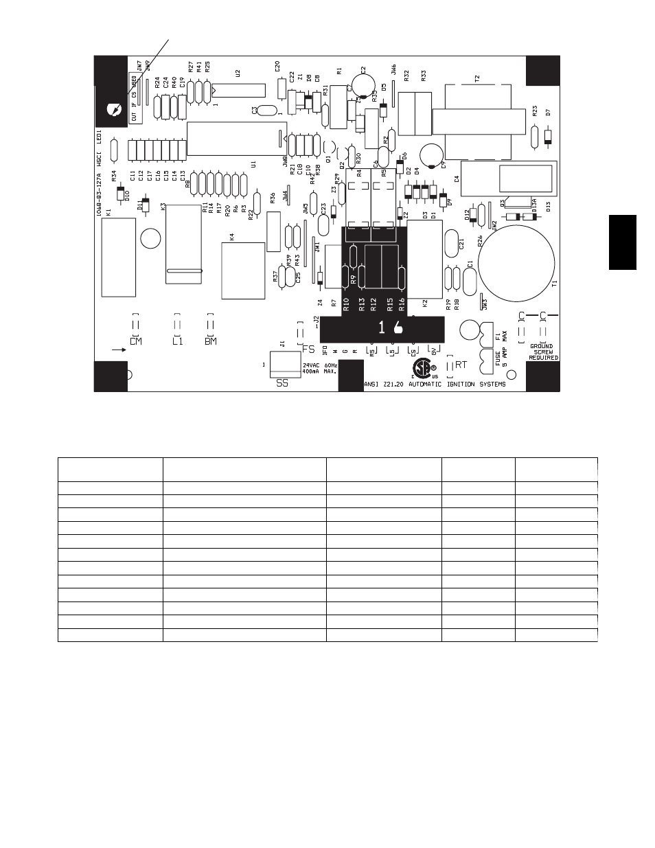
Red LED-Status
C08452
Fig. 38 -- Integrated Gas Control (IGC) Board
Table 9 – IGC Connections
TERMINAL LABEL
POINT DESCRIPTION
SENSOR LOCATION
TYPE OF I/O
CONNECTION
PIN NUMBER
INPUTS
RT, C
Input power from TRAN 1
control box
24 VAC
—
SS
Speed sensor
gas section
analog input
J1, 1-3
FS, T1
Flame sensor
gas section
switch input
—
W
Heat stage 1
LCTB
24 VAC
J2, 2
RS
Rollout switch
gas section
switch input
J2, 5-6
LS
Limit switch
fan section
switch input
J2, 7-8
CS
Centrifugal switch (not used)
—
switch input
J2, 9-10
OUTPUTS
L1, CM
Induced draft combustion motor
gas section
line VAC
IFO
Indoor fan
control box
relay
J2, 1
GV
Gas valve (heat stage 1)
gas section
relay
J2, 11-12
580J
See also other documents in the category Bryant Conditioners:
- EVOLUTION 577D----A (40 pages)
- Packaged Air Handling Units 542J (4 pages)
- Air Handling Units 524J (36 pages)
- 591B (12 pages)
- Electric Air Conditoner 597C (28 pages)
- 599C (2 pages)
- PREFERREDT A07044 (80 pages)
- 502A (8 pages)
- 564A (20 pages)
- 702B (28 pages)
- 538J-18-1 (12 pages)
- 764A (24 pages)
- AIR CONDITIONERS 564A (20 pages)
- 561G (2 pages)
- PURON PLUS 598B (40 pages)
- R-410A 583B (30 pages)
- 538MNQ (10 pages)
- EVOLUTION 707D (4 pages)
- 463AAC008BA (19 pages)
- DURAPACK 558F (70 pages)
- 664A (4 pages)
- 479 D (13 pages)
- 569D (84 pages)
- Legacy Air Conditoner H3A (6 pages)
- 561S (2 pages)
- R-22 561G (6 pages)
- 594D (24 pages)
- 450D (10 pages)
- 574D (32 pages)
- DE LUXE 12 SEER 552A (36 pages)
- R-22 (52 pages)
- CD5A (8 pages)
- 564B (20 pages)
- Air Conditeners 180A (16 pages)
- 677C--A (36 pages)
- 559F (48 pages)
- LEGACY 564B (4 pages)
- s 123A (6 pages)
- 598A (8 pages)
- Air Cooled Condensing Units 569C (20 pages)
- 580J*08--14D (85 pages)
- Electric 594D (24 pages)
- 588A (28 pages)
- 577C (8 pages)