Rockwell Automation SA3100 Distributed Power System Drv Config,Program User Manual
Page 93
Configuring the UDC Module’s Registers
3-55
3.7.2 UDC Module Meter Port Setup Registers (Registers 1000-1017)
Registers 1001-1017 are used to configure the UDC module’s meter ports. This
configuration determines what variables from the UDC module’s dual port memory are
to be displayed on the meter ports at the end of the UDC scan. At system power-up,
the output values of the ports are reset to zero.
To map a UDC variable to a specific meter port at power-up, refer to table 3.8 and use
the following procedure. Note that the setup register configurations are retained
during a Stop All.
For each meter port:
Step 1. Place the register number of the variable you wish to display in the
appropriate Variable Register Number register.
Step 2. If an individual bit of the register is to be displayed, enter it in the Bit Number
register as 100 (bit 00) to 115 (bit 15).
Step 3. Place the value (maximum 32767) that will represent +10V in the Maximum
Value register.
Step 4. Place the value (minimum -32768) that will represent -10V in the Minimum
Value register.
Step 5. Set register 1001 (Initiate Change in Setup) equal to a non-zero value to
store the new setup register configurations in memory.
The UDC module’s meter ports are updated once per scan once the UDC task is
running and CCLK is on. They are updated every 5 milliseconds when CCLK is off.
UDC meter ports can also be set up on-line using the “Setup UDC” selection from the
Monitor menu as described in the AutoMax Programming Executive instruction
manual. This setup is valid only until there is a power cycle, in which case the meter
ports default to outputting zero voltage and the UDC Setup screen is cleared on
power-up.
Refer to the UDC module instruction manual (S-3007) for more information about the
UDC module’s meter ports.
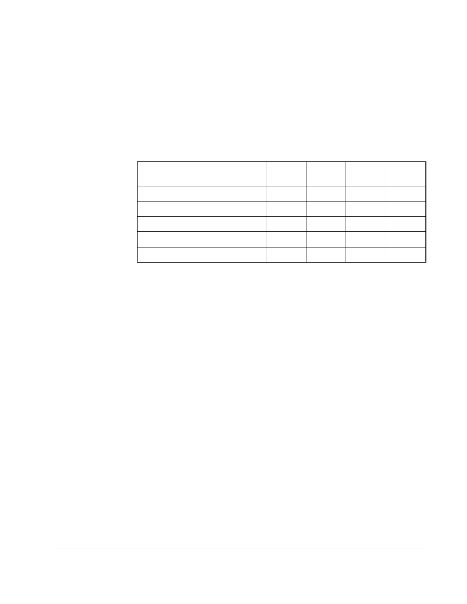
Table 3.8 – UDC Module Meter Port Setup Registers
UDC Module Meter Port
Setup Registers
Meter
Port 1
Meter
Port 2
Meter
Port 3
Meter
Port 4
Change Setup Register
1001
1001
1001
1001
Variable Register Number Register
1002
1006
1010
1014
Bit Number Register
1003
1007
1011
1015
Maximum Value Register
1004
1008
1012
1016
Minimum Value Register
1005
1009
1013
1017