2 cs300 equipment power supplies – Rockwell Automation T8094 8000 Series TMR System Safety Manual User Manual
Page 102
SAFETY MANUAL
D oc N umber T8094
I ssue 27 – June 2013
Page 81 of 103
The Trusted
TM
chassis is designated Chassis 1. The original primary rack of the CS300
controller which was designated Chassis 1 is now logical Chassis 2, Chassis 2 (if
present) is now logical Chassis 3, and so on. All communications to workstations and
DCS systems are through the Trusted
TM
communication interfaces.
For more details about the CS300 bridge module refer to PD-T8162.
9.6.2 CS300 Equipment Power Supplies
Any power supply used with the T8162 CS300 Bridge module must conform to IEC
61131 Part 2, SELV/PELV, EN61010 or EN60950.
Note: The power supply monitors its output voltage and temperature. When either is
outside their specified limits then a fault is declared and is reported by a power supply
front panel indicator. The CS300 bridge module also monitors the power output and
will detect an over voltage and declare a fault.
9.6.3 PI-616/PI-716 Digital Input Board
When the PI-616/PI-716 digital input board is used for safety-related applications, it
must be configured for 3-2-0 degradation and arranged in one of the tested
configurations shown in Figure 9 and Figure 10.
9.6.4 PI-632/PI-732 Analogue Input Board
The analogue input board does not have integrated calibration drift monitoring or a
calibration maintenance alarm. This must be implemented in the migrated application.
The board must be configured for 3-2-0 degradation and used as shown in Figure 11.
When the safety system’s availability is analysed, then the isolated analogue input
amplifier fitted to the termination panel must be considered in the same way as the
input field sensors.
The analogue input cards must have their calibration checked during the normal plant
maintenance cycle. The analogue calibration check must be completed, at a minimum,
one time every year.
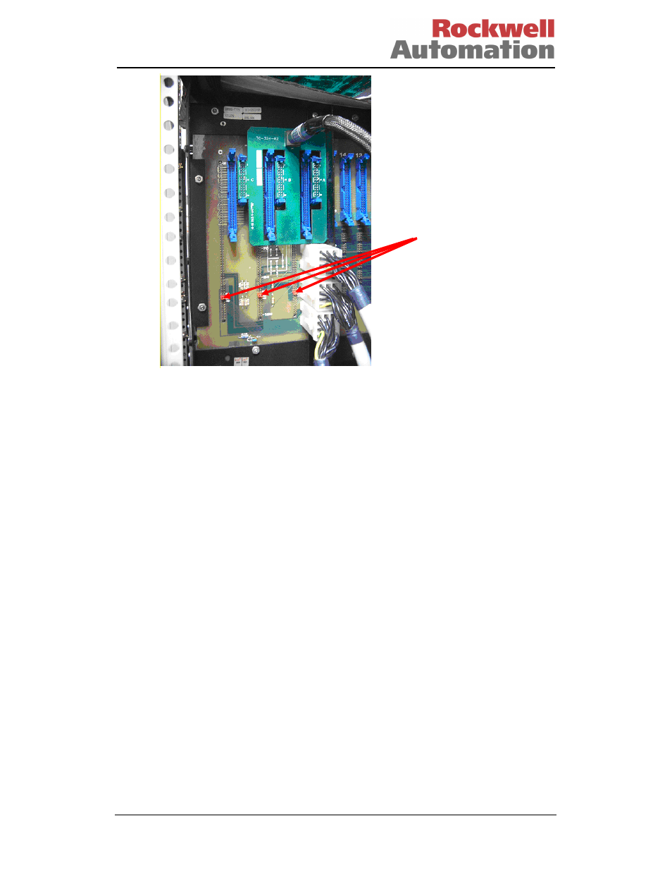
Address
Jumpers