Step 12: remove phase units from mounting base, Step 13: remove emc shield unit – Rockwell Automation 20D Balancing Resistor Kit - 690V Fr 13 PowerFlex 700AFE & Fr 13/14 PowerFlex 700H/S User Manual
Page 8
8
Rockwell Automation Publication PFLEX-IN028A-EN-P - February 2012
Balancing Resistor Kit for 600/690V Frame 13 PowerFlex 700AFE and 600/690V Frame 13 and 14 PowerFlex 700H/700S AC Drives
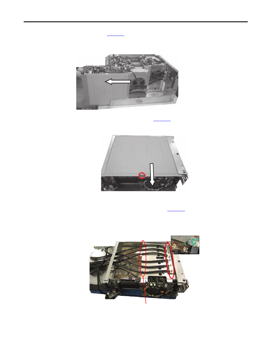
Step 12: Remove Phase Units
from Mounting
Base
See
and slide the phase unit off of the mounting base.
Figure 12 - Sliding Phase Unit Off of Mounting Base
and slide off the side cover.
Figure 13 - Removing Phase Units Side Cover
Step 13: Remove EMC Shield
Unit
Unfasten the six (6) screws shown in
that connect the supply cables to
the EMC shield unit.
NOTE: Re-seat the Allen head screws so that they do not
get mixed up with other Allen head screws.
Figure 14 - Removing Supply Cable Screws
NOTE: Be careful when sliding phase unit out/back
in so that no wires or harnesses get damaged.
1. Slide phase unit out and onto a lift truck or wood
pallet of the same height as the phase unit is in
the mounting base.
2. Remove side cover while phase unit is vertical.
3. Place phase unit on its back with side cover up.
1 place
M5 x 10 screw
Tool: PZ2 – Head
Torque: 3.5 N•m
6 places
M8 x 20 screws
Tool: hexagonal socket head (size 6)
Torque: 20 N•m
NOTE: Cut Ty Wraps at six (6) locations.
During reinstallation:
1. Place Ty Wraps with head to side so that cover can slide on.
2. Only hand tighten the Ty Wraps.