Step 1: remove the power structure covers, Step 2: remove the asic- to-control pan cable set, Step 3: remove asic board cover – Rockwell Automation 20D Balancing Resistor Kit - 690V Fr 13 PowerFlex 700AFE & Fr 13/14 PowerFlex 700H/S User Manual
Page 3: Step 2: remove the asic-to-control pan cable set
Rockwell Automation Publication PFLEX-IN028A-EN-P - February 2012
3
Balancing Resistor Kit for 600/690V Frame 13 PowerFlex 700AFE and 600/690V Frame 13 and 14 PowerFlex 700H/700S AC Drives
Step 1: Remove the Power
Structure Covers
Unfasten the twelve (12) screws shown in
and remove the protective
front and terminal covers from the power structure.
Figure 1 - Removing the Protective Front and Terminal Covers
Step 2: Remove the ASIC-
to-Control Pan
Cable Set
Disconnect the wire harness from the ASIC board, and remove the wire harness
from the power structure. Note the wire harness connectors and board
connection identification for reinstallation.
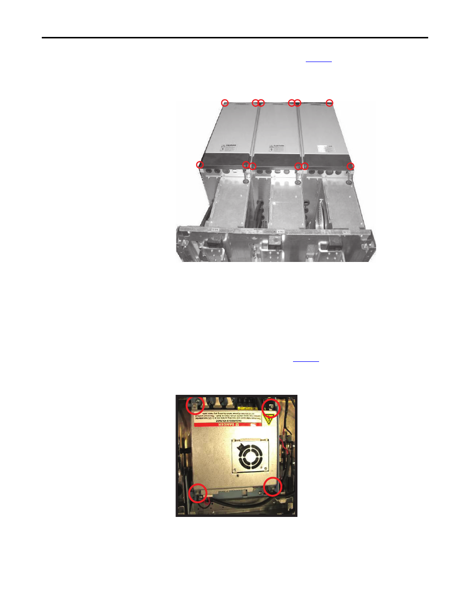
Step 3: Remove ASIC Board
Cover
Unfasten the four (4) screws shown in
Figure 2
and remove the ASIC board sheet
metal cover.
Figure 2 - Removing ASIC Board Cover
12 places
M5 x 16 screws
Tool: PZ2
Torque: 1.5 N•m
4 places
M4 x 8-DIN6900-3-Combi-Delta-TX hexagonal screws
Tool: PZ2 – Head
Torque: 4 N•m
NOTE: Remove the X10 fan converter connector on the
ASIC board.