Step 9: remove dc bus bars, Step 10: remove voltage supply cables – Rockwell Automation 20D Balancing Resistor Kit - 690V Fr 13 PowerFlex 700AFE & Fr 13/14 PowerFlex 700H/S User Manual
Page 6
6
Rockwell Automation Publication PFLEX-IN028A-EN-P - February 2012
Balancing Resistor Kit for 600/690V Frame 13 PowerFlex 700AFE and 600/690V Frame 13 and 14 PowerFlex 700H/700S AC Drives
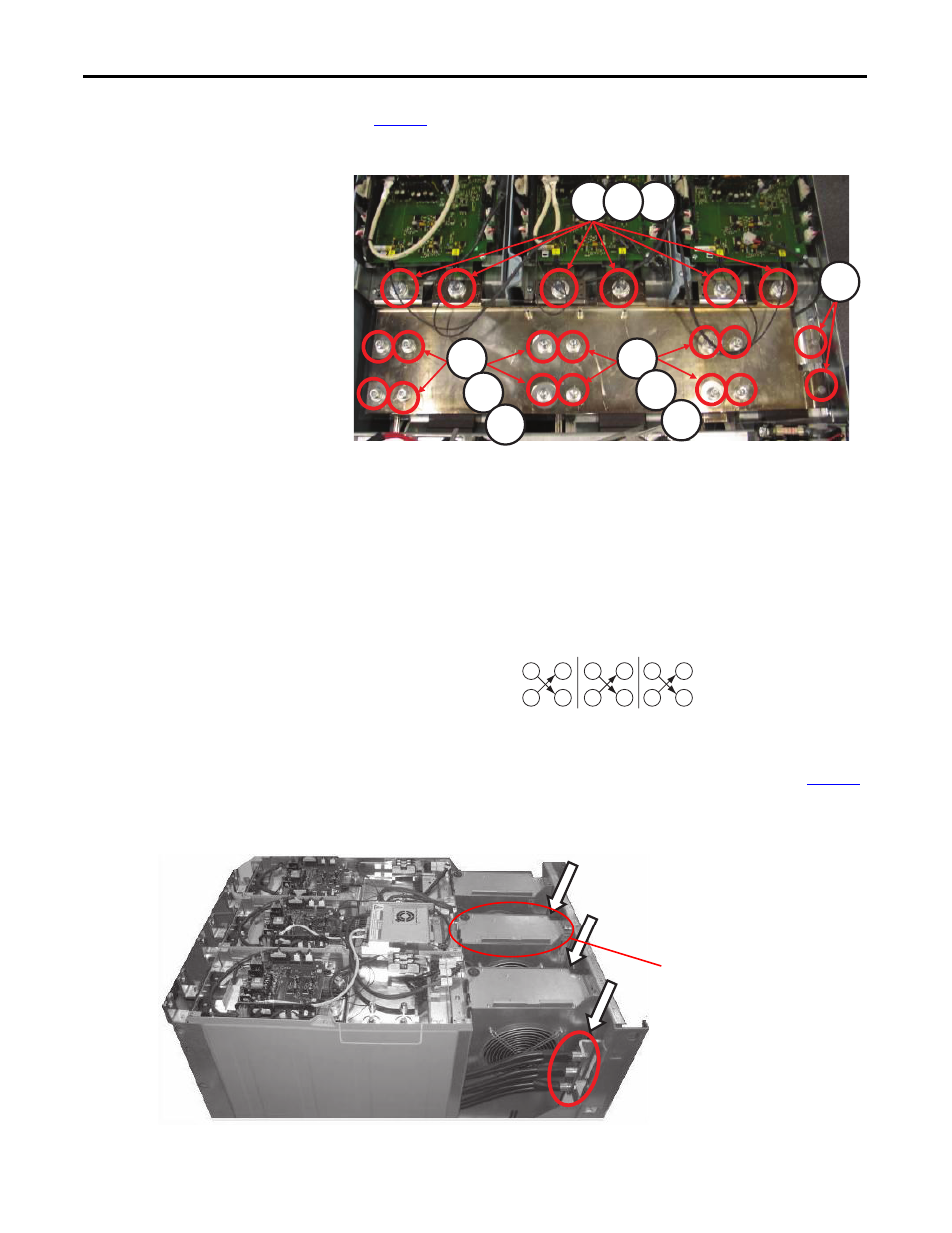
Step 9: Remove DC Bus Bars
See
Figure 8
and remove the DC bus bars and insulators between the bars.
Figure 8 - Removing DC Bus Bars
Step 10: Remove Voltage
Supply Cables
Unfasten the nine (9) screws, spring washers, and flat washers shown in
Figure 9
and remove the voltage supply cables.
Figure 9 - Removing Voltage Supply Cable Screws
1
4
5
5
3
2
6
7
6
7
9
12
10
11
5
8
6
7
1
4
2
3
1. Remove screws M10 x 25, 6 places; Tool: hexagonal wrench (size 17); Torque: 20 N•m.
2. Remove flat washers, 6 places.
3. Remove spring washers, 6 places.
4. Remove screws M6 x 12, 2 places; Tool: PZ2 – Head; Torque: 5 N•m.
5. Remove screws M8 x 25, 12 places; Tool: hexagonal socket head (size 6); Torque: 20 N•m.
6. Remove flat washers, 12 places.
7. Remove spring washers, 12 places.
NOTE: When reinstalling the DC bus bars, torque the bus bars using the following torque
pattern. This diagonal style of tightening the screws evenly secures the bus bars.
DC Bus Bar Torque Pattern
9 places
M10 x 30 hexagonal screws
Tool: hexagonal wrench (size 17)
Torque: 40 N•m
9 places
Remove spring washers
Remove flat washers
Voltage Feedback
Board Location
NOTE: When reinstalling, re-torque the
voltage supply cables from the bottom. An 18
mm wrench may need to be used if the cable
starts to twist when re-torquing the cables.