Step 4: remove wires and cabling from asic board, Step 5: remove asic board assembly – Rockwell Automation 20D Balancing Resistor Kit - 690V Fr 13 PowerFlex 700AFE & Fr 13/14 PowerFlex 700H/S User Manual
Page 4
4
Rockwell Automation Publication PFLEX-IN028A-EN-P - February 2012
Balancing Resistor Kit for 600/690V Frame 13 PowerFlex 700AFE and 600/690V Frame 13 and 14 PowerFlex 700H/700S AC Drives
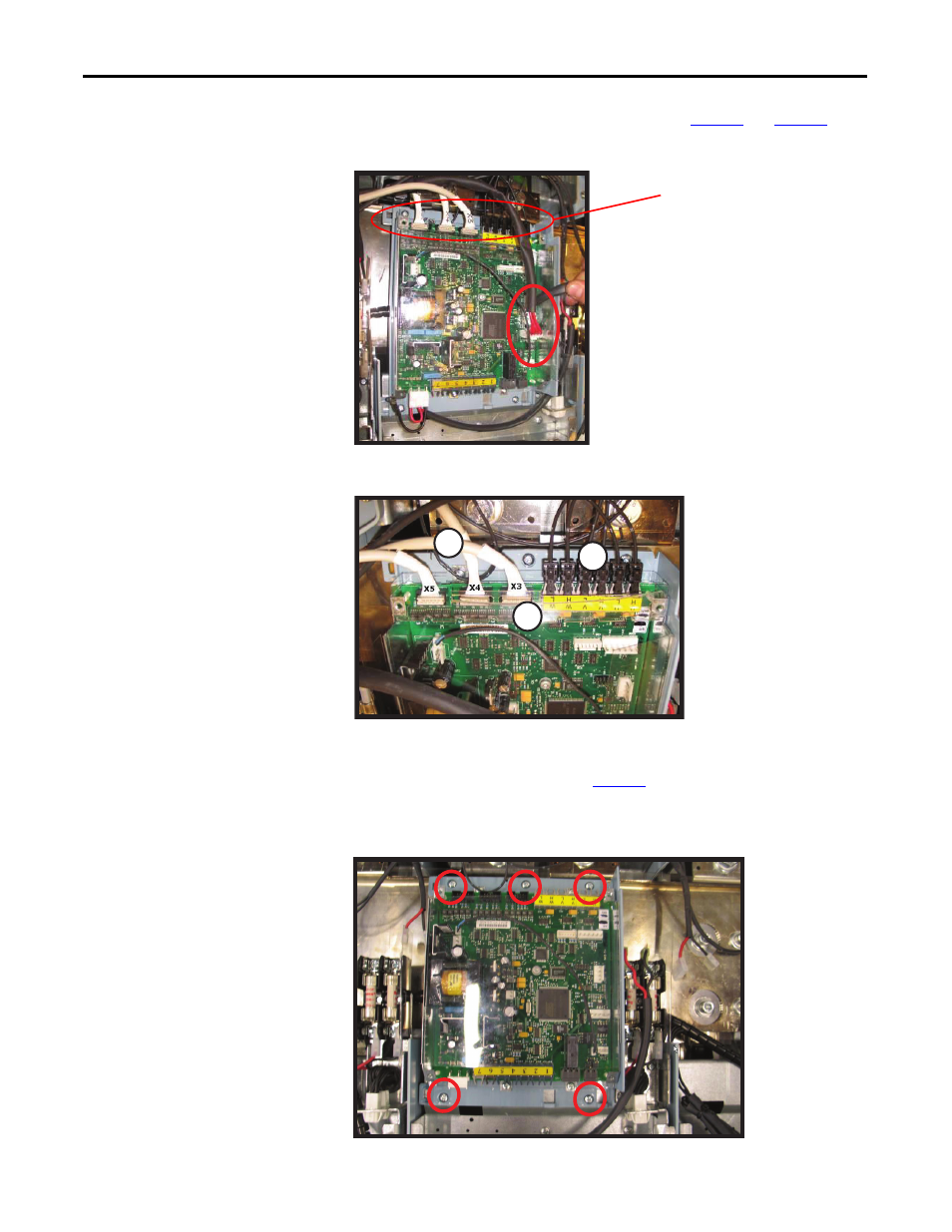
Step 4: Remove Wires and
Cabling from ASIC
Board
Remove the wires, plastic shield, and cables shown in
Figure 3
and
Figure 4
.
Figure 3 - Removing Wires from ASIC Board
Figure 4 - Removing Plastic Shield and Cables from ASIC Board
Step 5: Remove ASIC Board
Assembly
Unfasten the five (5) screws shown in
Figure 5
and remove the ASIC board
assembly.
Figure 5 - Removing the ASIC Board Assembly
Note the wire harness connectors
and board connection identification
for reinstallation.
Plastic Shield
1
2
3
1. Remove plastic shield.
2. Remove flat cables.
3. Remove fiber cables.
5 places
M4 x 8 screws
Tool: PZ2 – Head
Torque: 4 N•m