Rockwell Automation 20D Balancing Resistor Kit - 690V Fr 13 PowerFlex 700AFE & Fr 13/14 PowerFlex 700H/S User Manual
Page 7
Rockwell Automation Publication PFLEX-IN028A-EN-P - February 2012
7
Balancing Resistor Kit for 600/690V Frame 13 PowerFlex 700AFE and 600/690V Frame 13 and 14 PowerFlex 700H/700S AC Drives
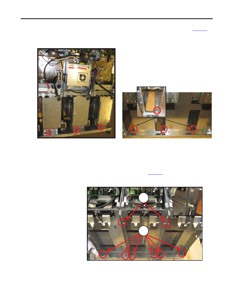
Step 11: Remove Power
Phase Units from
Assembly Base
Unfasten the six (6) mounting screws and conical washers shown in
and remove the power phase units from the assembly.
Figure 10 - Removing Screws from Bottom End of Power Phase Units
Unfasten the eight (8) screws shown in
Figure 11
that mount the phase units.
Figure 11 - Removing Top Head Screws of Phase Units
3 places
M8 x 20 socket head cap screws
Tool: hexagonal socket head (size 6)
Torque: 20 N•m
NOTE: When reinstalling, fasten these screws first to
ensure that the power modules are fully seated in the base.
3 places
M8 x 20 socket head cap screws
Tool: hexagonal socket head (size 6) - long extension recommended
Torque: 20 N•m
Remove M8 conical spring washers
1
2
1. Remove screws M8 x 20, 2 places; Tool: hexagonal socket head (size 6); Torque: 20 N•m;
and remove M8 nut; Tool: hexagonal wrench (size 13); Torque: 20 N•m
2. Remove screws M8 x 20, 6 places; Tool: hexagonal socket head (size 6); Torque: 20 N•m.