Trusted, Figure 27 switch configuration window, Figure 28 expander interface parameters window – Rockwell Automation T8082 Trusted Toolset Suite User Manual
Page 41: Toolset suite t8082
Trusted
TM
Toolset Suite T8082
Issue 14 Feb 10
PD-T8082
41
Once a Trusted
TM
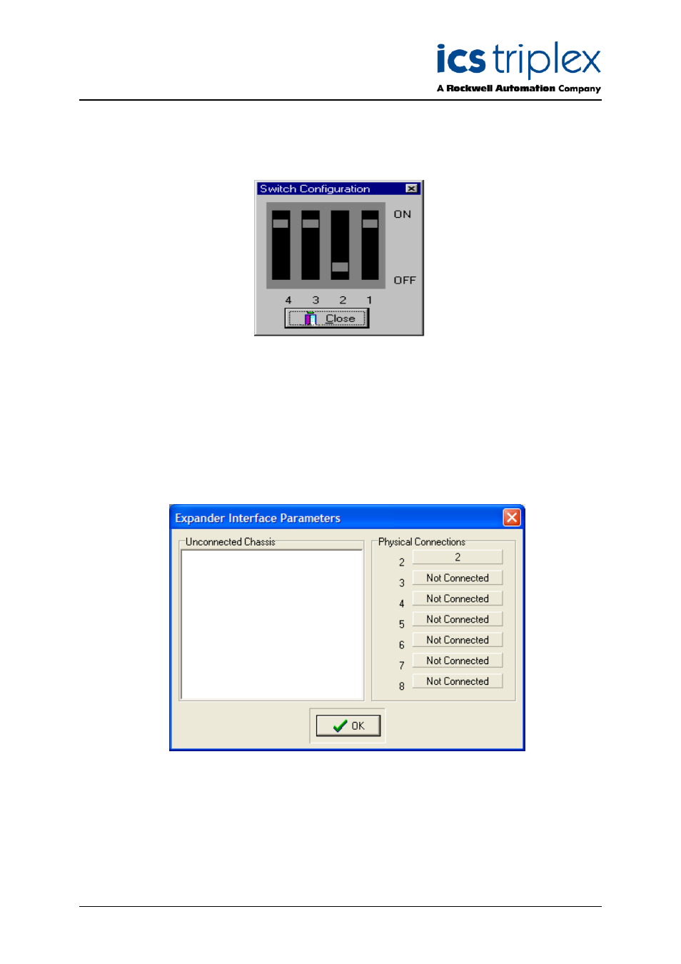
Expander Chassis has been connected, the Switch Config button on the Chassis
Connection window becomes active. Selecting this button will cause the Switch Configuration
window shown in Figure 27 below to be displayed.
Figure 27 Switch Configuration Window
This window shows the positions that the three DIP switches on the rear of the Expander Chassis
should be set in for Chassis 2. The first expansion chassis is always ID 2, the second ID 3 and so on.
If the switches are not set in the correct position, the Expander comms link will not function. Please
refer to product description PD-8300 Trusted
TM
TMR Expander Chassis for DIP switch details.
All Expander Chassis must be ‘connected’ to the ‘master’ Trusted
TM
Expander Interface Module as
described above. Confirmation that all chassis are connected may be obtained by placing the cursor
on the module in Slot 1 of the Controller Chassis and pressing the left-hand mouse button. This will
initiate the display shown in Figure 28 below.
Figure 28 Expander Interface Parameters Window
2.7. Trusted
TM
TMR Communications Interface Module ( 8151 / 8151B )