Threshold templates, Table 1 digital input threshold diagram, Trusted – Rockwell Automation T8082 Trusted Toolset Suite User Manual
Page 21: Toolset suite t8082
Trusted
TM
Toolset Suite T8082
Issue 14 Feb 10
PD-T8082
21
2.3.4.
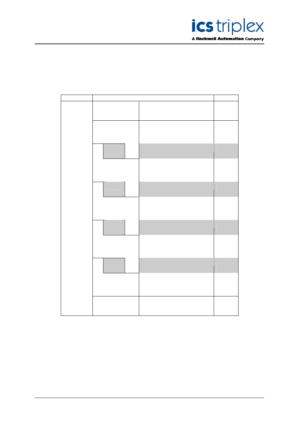
Threshold Templates
Input modules monitor and calculate the voltage level from the field at each channel to determine the
appropriate state to report to the TMR Processor. After the module has calculated the input channel
voltage, a state is then determined based on the channel threshold settings. There are 8 possible
states (0 to 7). An example of these state thresholds is shown in Table 1 below.
Threshold
Description
State
T
max
The voltage is above the
maximum for the module (set
in manufacture ).
6
Tmax
S/C
Short circuit. The voltage level
indicates a short circuit field
loop
5
T8
4 or 5
T7
CC
Closed contact.
4
T6
3 or 4
T5
IND
Indeterminate, this voltage
indicates an error condition.
3
T4
2 or 3
T3
OC
Open contact.
2
T2
1 or 2
T1
O/C
Open circuit. The voltage level
indicates an open circuit field
loop condition.
1
Tmin
T
min
The voltage is below the
minimum for the module ( set
in manufacture ).
0
Table 1 Digital Input Threshold Diagram
States 0 to 6 are based on the calculated voltage. One additional state (7) is reported when the
module has completely failed. The description of the states shown above is in terms of a line
monitored digital input switch configuration.
There are fixed minimum (Tmin) and maximum (Tmax) thresholds for the module, but each channel
has eight configurable thresholds as illustrated above. Each state transition has a hysteresis shown by
the grey areas in the diagram.