Rockwell Automation GV3000/SE AC Drive Ver. 6.06 Hdwe Ref., Installation, and Troubleshooting Manual User Manual
Page 61
Installing Input Power Wiring
5-5
5.4 Installing Power Wiring from the AC Input Line to the
Drive’s Power Terminals
Use the following steps to connect AC input power to the drive:
Step 1. Wire the AC input power leads by routing them according to drive type. Refer
to figures 4.1 through 4.7. Tables 3.3 through 3.8 contain the recommended
power wiring sizes.
Note that on 200-400 HP drives, knockouts for conduit installation are not
provided. If incoming power is 380 or 415 VAC, the fan transformer taps must
be changed before the power leads are connected. See section 5.6.
Step 2. Connect the three-phase AC input power leads (three-wire 380-460 VAC) to
the appropriate terminals.
On 1-60 HP drives, connect the AC input power leads to terminals R/L1,
S/L2, T/L3 on the power terminal strip.
On 60-150 HP drives, connect the AC input power leads to terminals 1L1,
1L2, and 1L3.
On 200-400 HP drives, connect the AC input power leads to terminals R, S,
and T.
Step 3. Tighten the AC input power terminals to the proper torque as shown in table
5.2.
!
ATTENTION: Do not route signal and control wiring with power wiring in
the same conduit. This can cause interference with drive operation.
Failure to observe this precaution could result in damage to, or
destruction of, the equipment.
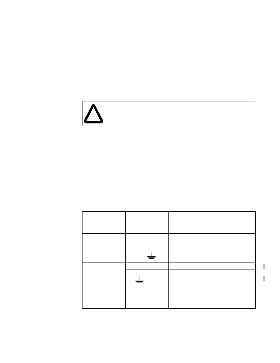
Table 5.2 – Terminal Tightening Torques
Drive
Terminals
Maximum Tightening Torque
1-25HP
All
1.08 Newton-meters (9.5 in-lb)
25-60HP
All
13.5 Newton-meters (10 ft-lb)
60-100HP
1L1, 1L2, 1L3
U, V, W
45,47
10 Newton-meters (7.4 ft-lb)
PE,
2.5 Newton-meters (1.8 ft-lb)
100-150HP
1L1, 1L2, 1L3, PE
34 Newton-meters (25 ft-lb)
U, V, W
, 45, 47
34 Newton-meters (25 ft-lb)
200-400HP
R/L1, S/L2, T/L3
U/T1, V/T2, W/T3
DC-, DC+
GND
34 Newton-meters (25 ft-lb)