Rockwell Automation GV3000/SE AC Drive Ver. 6.06 Hdwe Ref., Installation, and Troubleshooting Manual User Manual
Page 31
About the Drive
2-17
Step 3. Verify that the DC bus voltage is zero by following the procedure in section
9.3.
Step 4. Locate jumper J17 on the Regulator board. Refer to figures 2.9, 2.10, and
2.11.
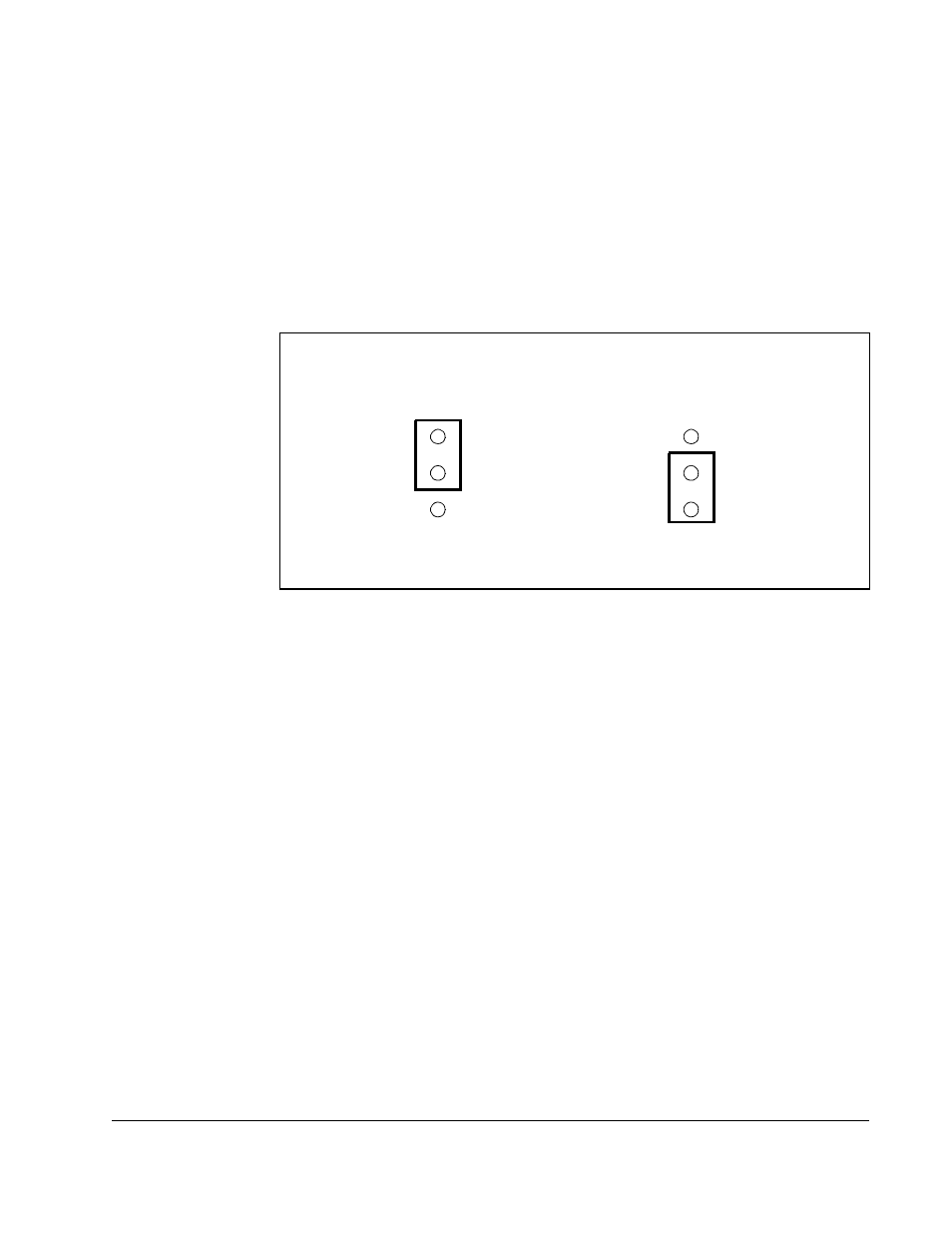
Step 5. Locate pin 1 on jumper J17. Move the jumper to the desired setting as shown
in figure 2.13.
Step 6. Reattach the cover. On 200-400 HP drives, close the outer cabinet door.
Step 7. Reapply input power.
Step 8. Verify that parameter P.012 is set correctly for either speed or current.
2.8.2 Wiring the Terminal Strip
The terminal strip on the Regulator board provides terminals for connecting customer
I/O devices. See figures 2.9, 2.10, 2.11, and 2.14. The following terminals are
provided:
•
Terminals 1-3: RS-232 connections
•
Terminals 4-9: encoder connections
•
Terminals 10-11: analog output connections
•
Terminals 12-15: analog speed/torque reference connections
•
Terminals 16-25: 24V DC digital input connections
•
Terminals 26-27: snubber resistor braking control connections
(1-10 HP Regulator boards only) for older Snubber Resistor Braking Kits
(for example, the M/N 2DB4010 series)
•
Terminals 28-31: status relay connections
Figure 2.13 – Jumper J17 Settings for Analog Outputs
J17
J17
10 VDC
Voltage Output Option
Pins 2-3
Current Output Option
Pins 1-2
4-20 mA
(default)