Power cable interconnection overview – Rockwell Automation 6000 PowerFlex Medium Voltage Variable Frequency Drive Installation Instructions User Manual
Page 56
56
Rockwell Automation Publication 6000-IN006A-EN-P - April 2014
Chapter 4
Drive Electrical Interconnection
Power Cable Interconnection
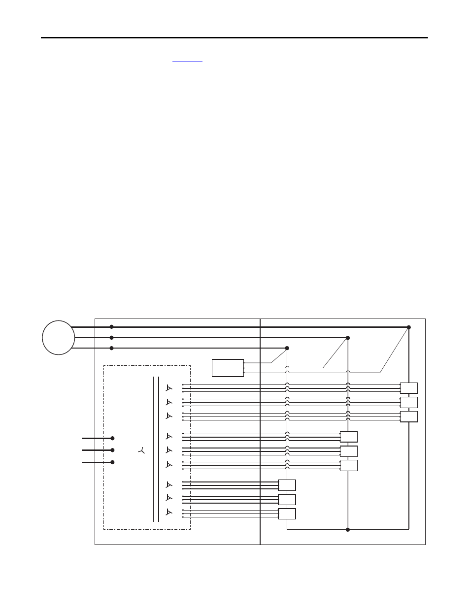
Overview
provides a three-line drawing overview of the power cable
interconnections between the power modules (PC XX) in the Power Module/
LV Control cabinet and the secondary windings of the isolation transformer in
the Isolation Transformer cabinet. The number of power modules is dependent
solely on output (motor) voltage:
•
9 power modules for 3/3.3 kV
•
18 power modules for 6/6.6 kV
•
27 power modules for 10 kV
It also shows the connection point from the U, V, and W motor output phases
from the power module array to the voltage sensing board cables and the motor
cables.
The isolation transformer secondary windings as shown do reflect the actual
orientation on the isolation transformer.
The Power Module/LV Cabinet orientation is optimized for drawing clarity. To
better understand the physical orientation, the components and connections
shown in the Power Module/LV Control Cabinet would be rotated 90º counter
clockwise. The U phase is the top horizontal row, the V phase is the middle
horizontal row, and the W phase is the bottom horizontal row.
Refer to the Electrical Drawing for actual wire number designations.
Figure 35 - Power Cabling Overview (3.3 kV Fixed-mounted Power Module Configuration)
L11
L12
L13
A1
B1
C1
A2
B2
C2
A3
B3
C3
A4
B4
C4
A5
B5
C5
A6
B6
C6
A7
B7
C7
A8
B8
C8
A9
B9
C9
U
V
W
PC A1
PC A2
PC A3
PC B1
PC B2
PC B3
PC C1
PC C2
PC C3
U
V
W
Input power
3-phase AC
any voltage
Isolation Transformer
Motor
Voltage Sensing
Board
Isolation Transformer Cabinet
Power Module/LV Control Cabinet