Mounting clearance distance, Mounting requirements, Mounting clearance distance mounting requirements – Rockwell Automation 6000 PowerFlex Medium Voltage Variable Frequency Drive Installation Instructions User Manual
Page 16
16
Rockwell Automation Publication 6000-IN006A-EN-P - April 2014
Chapter 1
Shipping and Handling Procedures
Mounting Clearance Distance
Install the drive with appropriate clearance distances on all sides to ensure proper
operation and allow maintenance of the drive.
Mounting Requirements
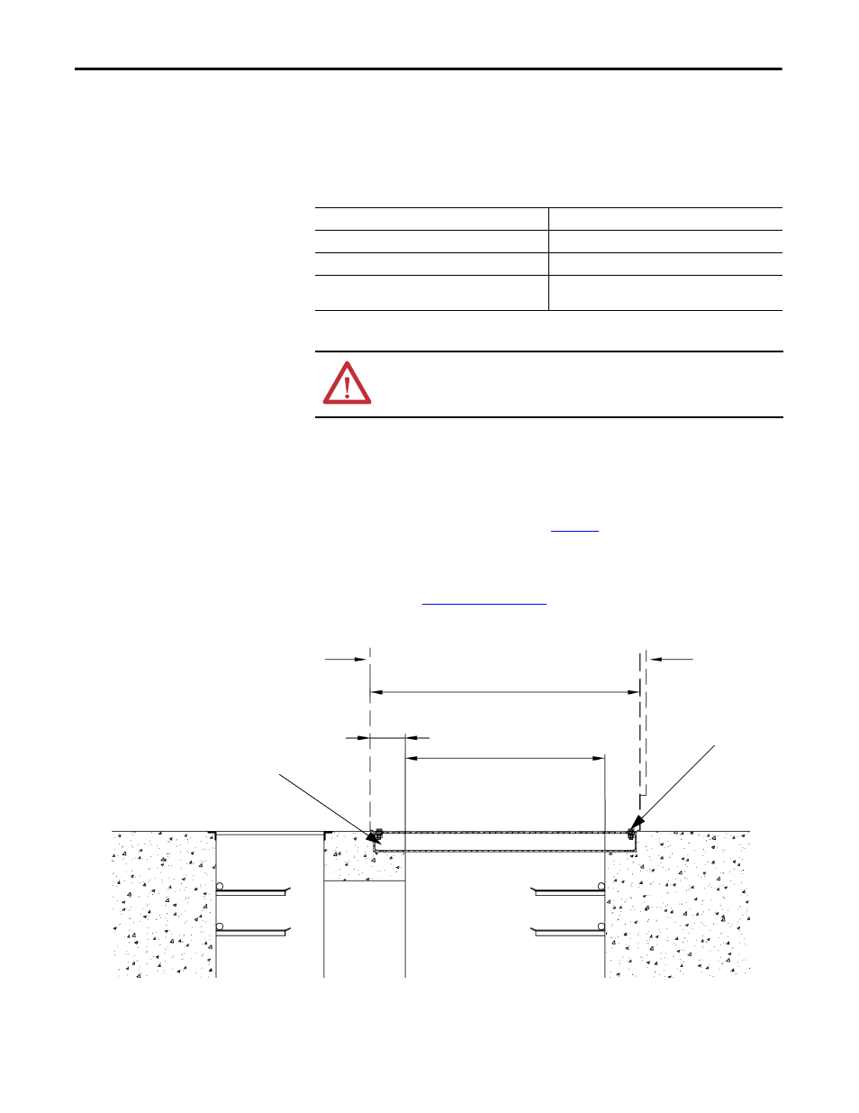
The base must be smooth, flat and level. If power cabling is entering from below,
and a cable trench system is used, refer to
. The base structure of the drive
cabinet may be constructed with #10 channel steel, approximately
100 x 48 x 5.3 mm (3.9 x 1.9 x 0.2 in.). Dimension pairs reflect the 1300 mm or
1500 mm deep cabinet configurations and the corresponding Drive Cable
Trench depth. See
Figure 3 - A typical cross-sectional view of the trench system
Embed the channel steel base profile in the base with its top surface flush with
ground level, or protruding slightly above ground level.
Table 3 - Minimum Mounting Clearance Distances
Location
Minimum Distance Required, approx.
In Front
• 1500 mm (60 in.)
Behind
• 1000 mm (39 in.)
Above
(1)
(1) Distance above is measured from the top plate of the drive cabinet (excludes height of fan housing).
• 400 mm (16 in.) without ducting requirements
• 1000 mm (39 in.) with ducting requirements
ATTENTION: An incorrectly applied or installed drive can result in component
damage or reduction in product life. Ambient conditions not within the
specified ranges may result in malfunction of the drive.
150 mm
(6 in.)
950 mm (37 in.) or
1150 mm (45 in.)
1300 mm (51 in.) or
1500 mm (59 in.)
Cabinet body is
bolted to the
channel steel base
Main Cable Trench
Cable Passage
Drive Cable Trench
Back
Front
Channel Steel Base