Rockwell Automation 61C542 Voltage Input module User Manual
Page 25
4Ć7
4.1.7
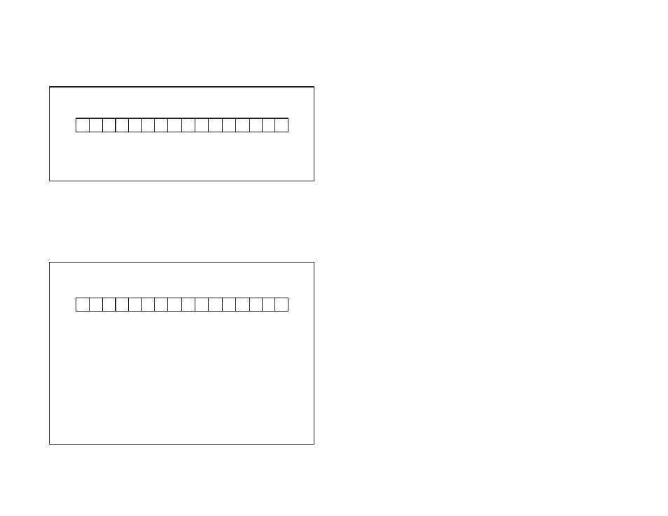
Channel Configuration Status Register (Register 21)
Register 21 indicates whether or not a channel has been configured.
See figure 4.7. A bit is set in this register when a channel receives a
correct write configuration command. Note that if two channels are
configured as a differential pair, both channel status bits will be set.
The bit remains set until it is cleared by a reset configuration
command from register 31.
Register 21
Bits 0Ć15
15 14 13 12 11 10 9
8
7
6
5
4
3
2 1
0
Bit 5 = Channel 5
Bit 6 = Channel 6
Bit 7 = Channel 7
Bit 8 = Channel 8
Bit 9 = Channel 9
Bit 10 = Channel 10
Bit 11 = Channel 11
Bit 12 = Channel 12
Bit 13 = Channel 13
Bit 14 = Channel 14
Bit 15 = Channel 15
Bit 0 = Channel 0
Bit 1 = Channel 1
Bit 2 = Channel 2
Bit 3 = Channel 3
Bit 4 = Channel 4
R
R
R R R R
R R
R
R
R
R
R
R R R
Figure 4.7 Ć Channel Configuration Status Register
4.1.8
Configuration Status Register (Register 22)
Register 22 provides the status of the configuration command issued
by register 31. See figure 4.8. Bit 15 is set in this register whenever a
channel receives a configuration command. Error bit 14 will be set if
an incorrect configuration command is detected.
Bit 0 = Channel Number Error
Bit 1 = Illegal Running Average Number Error
Bit 2 = Low Low Alarm Value Is Not the Lowest
Bit 3 = High Alarm Value Is Not Larger Than The Low Alarm Value
Bit 4 = High High Alarm Value Is Not the Highest
Bit 5 = Alarm Value is Out Of Range Of The Scaling Range
Bit 6 = Illegal Configuration Command
Bit 7 = READY State Not Enabled
Bit 8 = Maximum Scaling Value Must Be At Least 100 Greater Than The
Minimum Scaling Value
Bit 9 = Square Root Extraction is Only Valid in the Unipolar Mode
Bits 10 to 13= Not Used
Bit 14 =ĂConfiguration Error
Bit 15 =ĂConfiguration Is Complete
Register 22
Bits 0Ć15
15 14 13 12 11 10 9
8
7
6
5
4
3
2 1
0
R
R - - - - R R
R
R
R
R
R
R R R
Figure 4.8 Ć Configuration Status Register