2 electrical description – Rockwell Automation 61C346 4 Input 0-10V Analog Rail Module User Manual
Page 14
2Ć4
2.2
Electrical Description
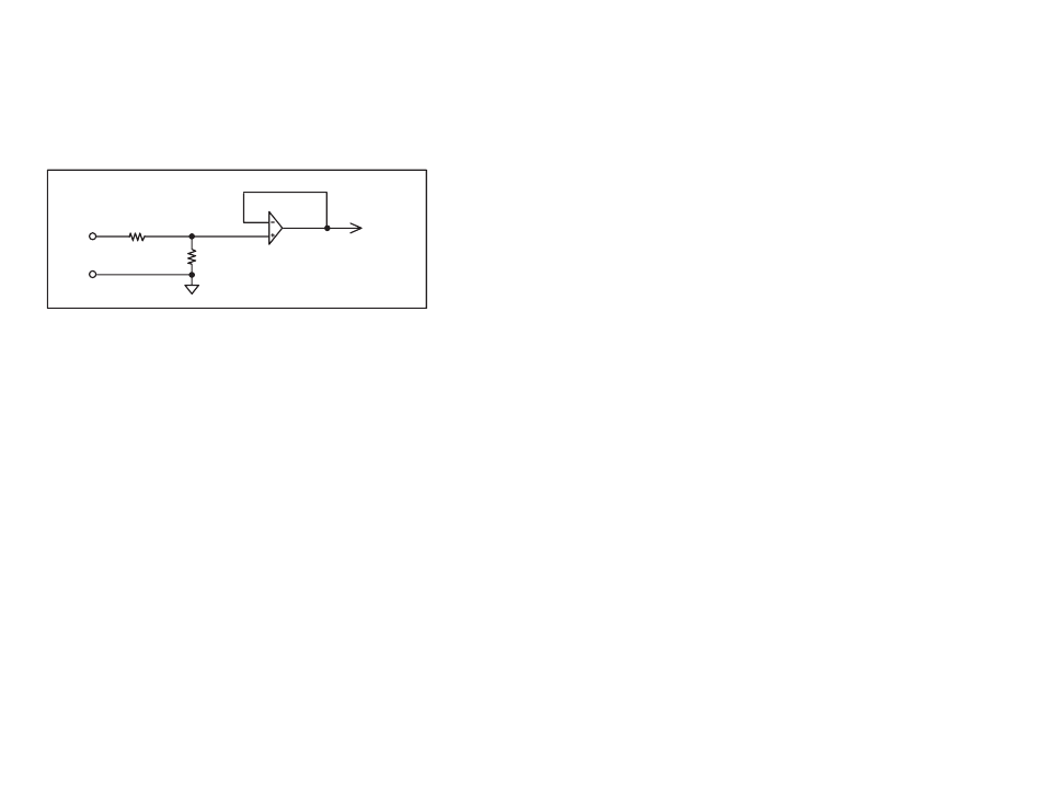
The Analog Rail module contains four analog input channels that
convert 0Ć10V analog input signals to proportional values between 0
and 4095, equal to 12 bits of digital data. Input signals are filtered
through a second order lowĆpass filter.
The A/D conversions are triggered by the actual I/O update
sequences. The conversion rate is therefore dependent upon the
scan time of the application task. See figure 2.2 for a typical input
circuit.
4
to A/D
converter
VĆIN
VĆOUT
90K
90K
Figure 2.2 ĆTypical Input Circuit
The Analog Rail module is factory calibrated and requires no
offset/gain adjustment. All four analog input channels are referenced
to the same common. This common is isolated from both the external
power supply and the I/O port connection.
The module incorporates extensive diagnostics. In Rail mode, check
bits are monitored for accuracy on every transfer of data between the
host and the module. In Local Head mode, parity bits are monitored
for accuracy on every transfer of data. A Rail fault LED on the
processor, Remote Head, or Local Head will be illuminated if the
check bits or parity bits are wrong and all transmission will stop after
n retries, where n is a value determined by the host's software
(average n = 4 for AutoMax; AutoMate n = 2).
In the event of a rail fault, the COM OK" LED on the module will go
off. If any power required by the module, i.e., the +5 Volts from the
I/O port required for communication, the external power supply, or
the power required by the Analog input section, is not within
specified limits, the PWR OK" LED will go off.