Wiring the sequence of events module, Wiring the sequence of events module -6 – Rockwell Automation 1756-IH16ISOE ControlLogix Sequence of Events Module User Manual
Page 32
Publication 1756-UM528A-EN-P - April 2004
3-6 Installing the Sequence of Events Module
Wiring the Sequence of
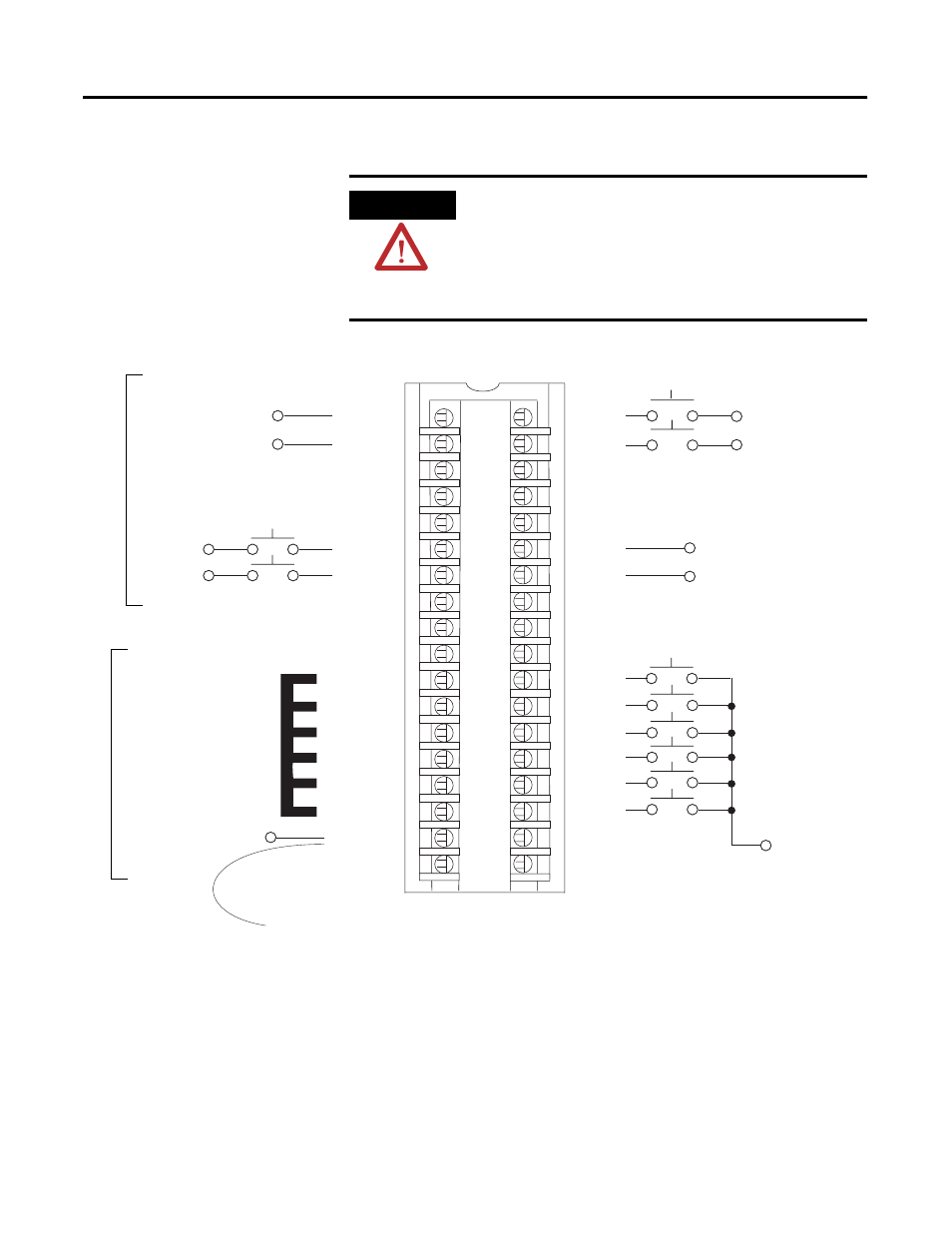
Events Module
Use Figure 3.7 to wire your Sequence of Events module.
Figure 3.7
WARNING
If you connect or disconnect wiring while the
field-side power is on, an electrical arc can occur.
This could cause an explosion in hazardous
location installations. Be sure that power is
removed or the area is nonhazardous before
proceeding.
40167-M
1
2
3
4
5
6
7
8
9
10
11
12
13
14
15
16
17
18
19
20
21
22
23
24
25
26
27
28
29
30
31
32
33
34
35
36
Non-isolated wiring
Isolated wiring
Daisy chain to other RTBs
DC (-)
Jumper bar
(Cut to length)
DC-5 (-)
DC-5 (+)
DC (+)
DC-0 (+)
DC-1 (+)
DC-0 (-)
DC-1 (-)
IN-0
IN-1
IN-2
IN-3
IN-8
IN-4
IN-5
IN-6
IN-7
Not used
IN-9
IN-10
IN-11
IN-12
IN-13
IN-14
IN-15
Not used
GND-0
GND-1
GND-2
GND-3
GND-8
GND-4
GND-5
GND-6
GND-7
Not used
GND-9
GND-10
GND-11
GND-12
GND-13
GND-14
GND-15
GND-15
DC-6 (-)
DC-6 (+)
NOTES:
1. All terminals with the same name are connected together on the module. For example, DC (-) can be connected to either terminal marked
GND-15.
2. When you use the second GND-15 terminal to daisy chain to other RTBs, always connect the daisy chain to the terminal directly connected
to the supply wire, as shown in the example above.
3. If separate power sources are used, do not exceed the specified isolation voltage.
4. Do not connect more than 2 wires to any single terminal.
5. The jumper bar part number is 97739201. Contact your local Rockwell Automation sales representative to order jumper bars, if necessary.
Sink input wiring
Source input wiring
Source input wiring
Sink input wiring