Understanding the module’s physical features, Understanding the module’s physical features -4 – Rockwell Automation 1756-IH16ISOE ControlLogix Sequence of Events Module User Manual
Page 14
Publication 1756-UM528A-EN-P - April 2004
1-4 What is the ControlLogix Sequence of Events Module?
Understanding the
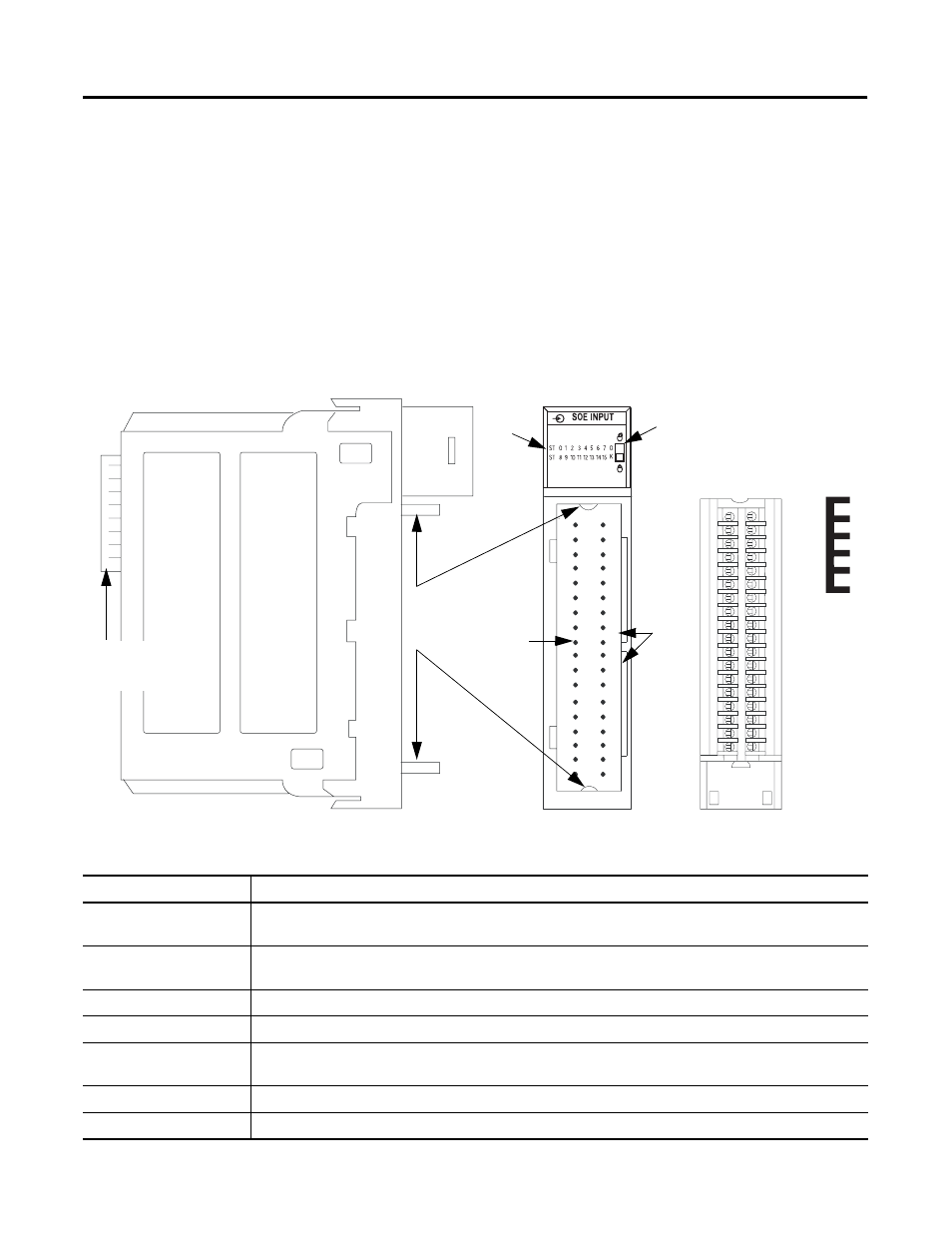
Module’s Physical Features
ControlLogix modules mount in a ControlLogix chassis and use a
Removable Terminal Block (RTB), or a Bulletin 1492 Interface Module
cable that connects to an IFM, to connect all field-side wiring. Before
you use your module, you should have already:
• installed and grounded a 1756 chassis and power supply. To
install these products, refer to the publications listed in
Table Preface.3 on page Preface-2.
• ordered and received an RTB or IFM and its components for
your application; neither RTBs nor IFMs are included with your
module purchase.
Figure 1.1
41623
O
K
Indicators
Locking tab
Removable terminal
block
Slots
for
keying
the
RTB
Connector
pins
Top and
bottom
guides
ControlLogix
backplane
Jumper
bar
Table 1.3 Physical Features on the ControlLogix Sequence of Events Module
Physical Feature:
Description:
Backplane connector
The backplane connector interface for the ControlLogix system connects the module to the ControlLogix
backplane.
Connector pins
Input/output, power and grounding connections are made to the module through these pins with the use of
an RTB or IFM.
Locking tab
The locking tab anchors the RTB or IFM cable on the module, maintaining wiring connections.
Slots for keying
Mechanically keys the RTB to prevent inadvertently making the wrong wire connections to your module.
Status indicators
Indicators display the status of communication, module health and input/output devices. Use these
indicators to help in troubleshooting.
Top and bottom guides
Guides provide assistance in seating the RTB or IFM cable onto the module.
Jumper bar
Device you can use to connect multiple points in non-isolated wiring application, as shown on page 3-6.