Plc-5 family processor – Rockwell Automation 1794-IJ2XT FLEX I/O Frequency Input Modules User Manual User Manual
Page 77
Publication 1794-6.5.11 - September 2011
Program Your Module with PLC Processors 67
PLC-5 Family Processor
Block transfer instructions with the PLC-5 processor use a control file and a
data file. The block transfer control file contains the data table section for
module location, the address of the block transfer data file and other related
data. The block transfer data file stores data that you want transferred to the
module (when programming a BTW) or from the module (when programming
a BTR).
The programming terminal prompts you to create a control file when a block
transfer instruction is being programmed. A different block transfer control
file is used for the read and write instructions for your module.
13
U
IJ2 BTR
Error Bit
B17:0
EN
BTR
BLOCK TRANSFER READ
Rack
Group
Slot
Data File
3
2
0
N18:101
Length
Control
0
B17:0
EN
BTW
BLOCK TRANSFER WRITE
Rack
Group
Slot
Data
3
2
0
N18:1
DN
Length
Control
0
B17:0
5
B17:0
B17:0
15
ER
DN
ER
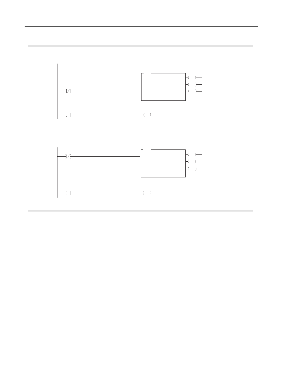
Rung M:0
The IJ2 module is located in rack 3, I/O group 2, slot 0. The control file is a 10 word file
starting at B17:0 that is shared by the BTR/BTW. The data obtained by the PLC3 processor is
placed in memory starting at location N18:101, and with the default length of 0, is 7 words long.
IJ2 BTR
Done Bit
IJ2 BTR/BTW
Control Block
The IJ2 module is located in rack 3, I/O group 2, slot 0. The control file is a 10 word file
starting at B17:0 that is shared by the BTR/BTW. The data sent by the PLC-3 processor to the
IJ2 module is from PLC memory starting at N18:1, and with the default length of 0,
is 8 words long.
13
IJ2 BTR
Error Bit
B17:0
IJ2 BTW
Done Bit
IJ2 BTR/BTW
Control Block
3
B17:0
3
B17:0
U
IJ2 BTW
Error Bit
IJ2 BTW
Error Bit
PLC-3 Processor
Program Example
45563