Rockwell Automation 1794-IJ2XT FLEX I/O Frequency Input Modules User Manual User Manual
Page 29
Publication 1794-6.5.11 - September 2011
Install Your FLEX I/O Frequency Input Module 19
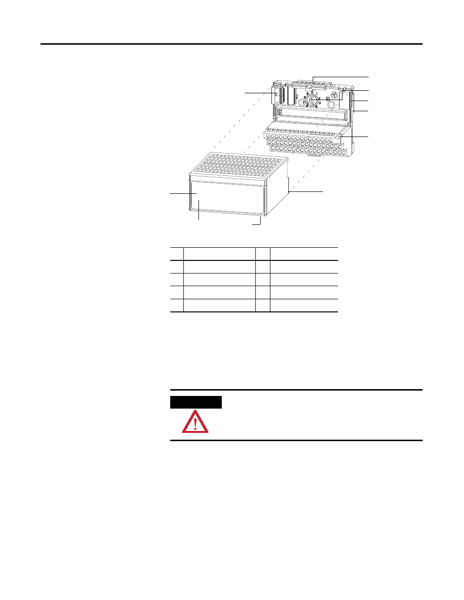
2. Make certain the FlexBus connector (1) is pushed all the way to the left
to connect with the neighboring terminal base or adapter.
You cannot install the module unless the connector is fully extended.
3. Make sure the pins on the bottom of the module are straight so they will
align properly with the connector in the terminal base unit.
4. Position the module (8) with its alignment bar (7) aligned with the
groove (6) on the terminal base.
5. Press firmly and evenly to seat the module in the terminal base unit.
The module is seated when the latching mechanism is locked into the
module.
6. Remove cap plug and attach another terminal base unit to the right of
this terminal base unit if required.
Make sure the last terminal base has the cap plug in place.
1
2
3
4
5
6
7
8
Label here or under here
40231
Description
Description
1
FlexBus connector
5
Base unit
2
Latching mechanism
6
Alignment groove
3
Keyswitch
7
Alignment bar
4
Cap plug
8
Module
ATTENTION
If you remove or insert the module while the backplane power is on,
an electrical arc can occur. This could cause an explosion in hazardous
location installations. Be sure that power is removed or the area is
nonhazardous before proceeding.