The flex i/o module in a logix control system, Gate input frequency input, Counter – Rockwell Automation 1794-IJ2XT FLEX I/O Frequency Input Modules User Manual User Manual
Page 13
Publication 1794-6.5.11 - September 2011
Overview of the Frequency Input Module 3
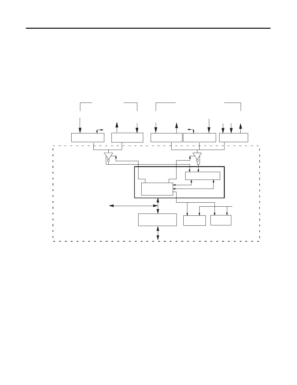
The primary use of the module is accurate, high-speed frequency
measurement. A high-speed internal clock is synchronized with the frequency
input to count over a user-selected sampling time or a user-defined number of
frequency input pulses.
All power for input devices (4 devices, 24 V DC @ 15 mA max) is supplied by
the I/O module.
The FLEX I/O Module in a
Logix Control System
The frequency input module performs high-speed frequency and/or scaling
calculation operations for various industrial applications. The module
interfaces with a FLEX I/O family adapter which then communicates with a
programmable controller processor that has block-transfer capability and
external I/O devices.
The adapter transfers data to the module (block transfer write) and from the
module (block transfer read) using BTW and BTR instructions in your ladder
diagram program. These instructions let the adapter read input values and
status from the module, and let you write output values and configure the
module mode of operation. The following illustration describes the
communication process.
500/50 mV
50 mV
Select
24V IEC 1+
24V IEC 1+
Magnetic
500/50 mV
Magnetic
Gate input
Frequency input
CRISP
Bus interface
Output 0
Output 1
Inter-processor
communication,
uP system 0/1
From
uP system 1
Data To/From FlexBus
Invert
Y/N
Invert
Y/N
Processing
Counter
Frequency / count data
uP system 0
Output control
Input control
Direction data
IEC 1+/Contact
Input
VORTEX
Vortex
3Vin 6Vin 24V power
IEC 1+/Contact
Input
50 mV
Select
GND
GND
Inputs
Module
FlexBus
24V Power
24Vpower
45388