Chapter summary – Rockwell Automation 1794-IJ2XT FLEX I/O Frequency Input Modules User Manual User Manual
Page 37
Publication 1794-6.5.11 - September 2011
Install Your FLEX I/O Frequency Input Module 27
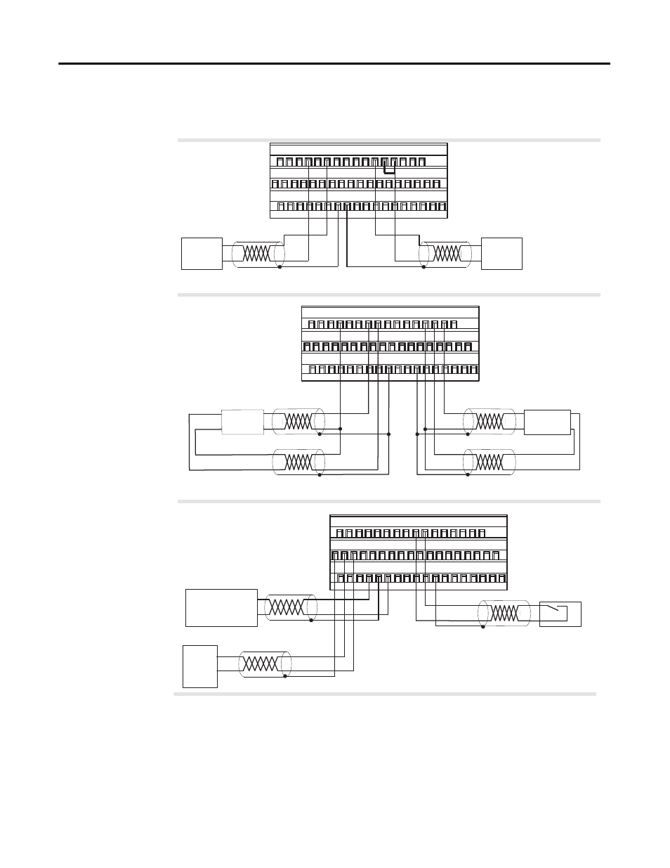
Examples of Wiring to a 1794-TB3G Terminal Base Unit
Chapter Summary
This chapter provided you with instructions on how to install the input
module in an existing programmable controller system and how to wire to a
terminal base unit.
24V DC IEC 1+ Proximity
0
1
2
3
4
5
6
7
8
9
10 11 12 13 14 15
16 17 18 19 20 21 22 23 24 25 26 27 28 29 30 31 32 33
34 35 36
37 38 39
40 41 42 43 44 45
46 47 48 49 50 51
+
-
Standard Magnetic Pickup
500 mV threshold (F0)
0
1
2
3
4
5
6
7
8
9
10 11 12 13 14 15
16
17 18
19 20 21 22 23
24 25
26 27 28 29 30 31 32 33
34 35 36 37 38 39 40 41 42 43 44 45 46 47 48 49 50 51
5
6
7
Power
In
Input
Device
+
-
+
-
+
-
Magnetic
Input
Device
10
12
Standard Magnetic Pickup
50 mV threshold (F0)
Standard Output (O0)
0
1
2
3
4
5
6
7
8
9
10 11 12 13 14 15
16 17 18 19 20 21 22 23 24 25 26 27 28 29 30 31 32 33
34 35 36 37 38 39 40 41
42 43 44 45 46 47 48 49 50 51
37
17
18
Important: When using a channel
for 50 mV sensor, jumper the
50/500 mV pin to the appropriate
RET.
Magnetic
Input
Device
40
41
3
3
42
14
12
12
13
45
6V Vortex Flowmeter
42
38
16
39
External
Power Supply #1
10-31.2V DC @ 1A
+
-
+
-
LOAD 0
9
Power
In
8
44
24V DC Contact Switch
Add external resistor
from 24V to F or G for
wire-off detection.
3
6V Vortex
Flowmeter
+
-
+
-
45347