Map data for the module, Frequency input module image table mapping – Rockwell Automation 1794-IJ2XT FLEX I/O Frequency Input Modules User Manual User Manual
Page 46
Publication 1794-6.5.11 - September 2011
36 Read and Write Configuration Maps for the FLEX I/O Module
Map Data for the Module
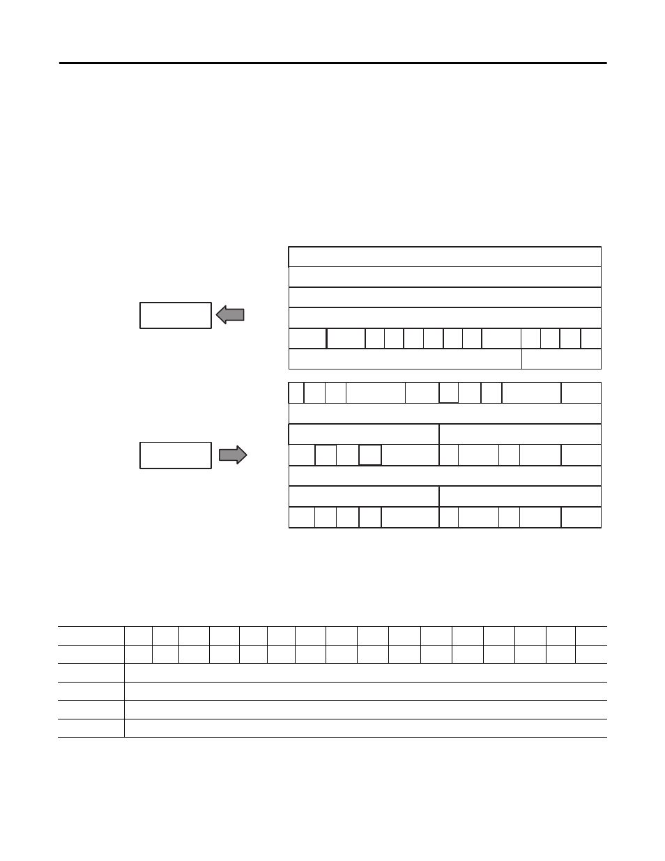
The following read and write words and bit/word descriptions describe the
information written to and read from the frequency input module. The
module uses up to 6 words of input data and up to 7 words of output data.
Each word is composed of 16 bits.
Frequency Input Module Image Table Mapping
Module Image
I/O Image
Frequency Channel 0
% Full Scale or Acceleration Channel 0
Diagnostics
Input size
Output size
0...7 Words
1...6 Words
Frequency Channel 1
% Full Scale or Acceleration Channel 1
GS
1
F/A
1
WO
1
MPA
1
DIR
1
GS
0
F/A
0
WO
0
MPA
0
DIR
0
R
R
R
Reserved
FR
1
MPM
1
R
NOPTS
1
LF
FR
0
MPM
0
NOPTS
0
SSM
CF
Minimum Freq or Absolute Value of Acceleration Channel 0
Frequency Scaling Divisor Channel 0
Frequency Scaling Multiplier Channel 0
F/A
AS0
WOFM
0
IS
UP0
MPDM
0
MFST
0
ACT 0
IFI
0
IGI
0
WOFF
0
WOFG
0
Minimum Freq or Absolute Value of Acceleration Channel 1
Frequency Scaling Divisor Channel 1
Frequency Scaling Multiplier Channel 1
F/A
AS1
WOFM
1
IS
UP1
MPDM
1
MFST
1
ACT 1
IFI
1
IGI
1
WOFF
1
WOFG
1
45351
Block Transfer Read Word Assignments
(Octal Bit)
17
16
15
14
13
12
11
10
07
06
05
04
03
02
01
00
Decimal Bit
15
14
13
12
11
10
09
08
07
06
05
04
03
02
01
00
0
Frequency 0…32,767 or 0.0…3,276.7 Channel 0
1
% Full Scale 0.0%…3,276.7% Channel 0 or Acceleration -32,768…+32,767 Channel 0
2
Frequency 0…32,767 or 0.0…3,276.7 Channel 1
3
% Full Scale 0.0%…3,276.7% Channel 1 or Acceleration -32,768…+32,767 Channel 1