Chapter 4, 5 – troubleshoot the module, Overview – Rockwell Automation 1794-IJ2XT FLEX I/O Frequency Input Modules User Manual User Manual
Page 61: Status indicators, Troubleshoot the module, Overview status indicators, Chapter
35
Publication 1794-6.5.11 - September 2011
Chapter
5
Troubleshoot the Module
Overview
This chapter provides a description of the different status indicators for the
frequency input module to help you troubleshoot.
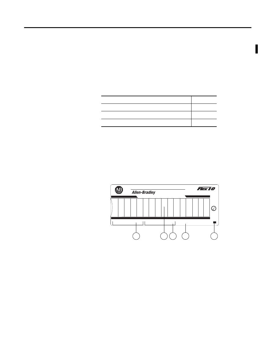
Status Indicators
The module has indicators for the following:
• Frequency and Gate Inputs
• Frequency and Gate Wire-Off Faults
• Alarm Outputs
When an input indicator (yellow) is lighted, it indicates that a valid signal
(active high or active low) is present at one of the input terminals.
When wire-off detection is enabled, and a wire-off fault is detected (24V DC
IEC 1+ input terminal only), a fault indicator (red) flashes at a rate of 1 Hz to
signal a fault condition. A wire-off fault signal is also sent to the backplane. A
flashing red fault indication means a valid wire-off condition for a 24V DC
IEC 1+ Input or a 24V DC contact switch input with a shunt resistor.
Topic
Page
Diagnostic Bits in Word 5 of the BTR File
FREQ
GATE
OK
0
FREQUENCY INPUT 2 CHANNEL
1
1794-IJ2
F
0
F
FREQ
GATE
1
F
1
F
OUT
0
OUT
1
A = Input indicator
B = Insertable label for writing individual I/O assignments
C = Wire-off fault indicator
D = Output indicator
E = Power/status indicator – indicates power applied to module and status of module
A
B
C
D
E
45348