Wiring information, Wiring the terminal base units (1794-tb3g shown) – Rockwell Automation 1794-IJ2XT FLEX I/O Frequency Input Modules User Manual User Manual
Page 30
Publication 1794-6.5.11 - September 2011
20 Install Your FLEX I/O Frequency Input Module
Wiring Information
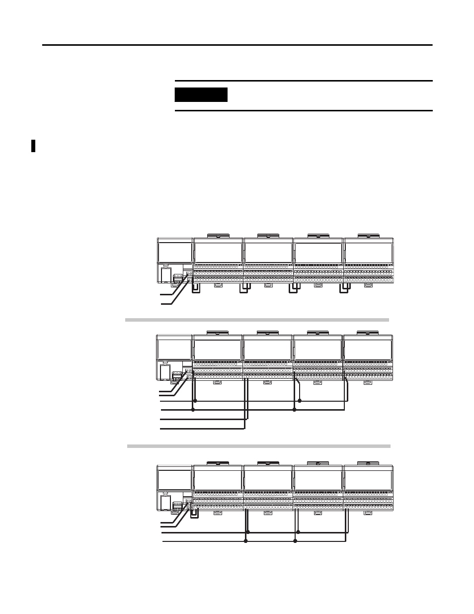
This section provides essential wiring information for the 1794-TB3G,
1794-TB3GK, and 1794-TB3GS terminal base units. It also includes
instructions for connecting wiring to the FLEX I/O module.
Wiring the Terminal Base Units (1794-TB3G shown)
IMPORTANT
The adapter is capable of addressing eight modules. Do not exceed a
maximum of eight terminal base units in your system.
Daisy-chaining
Individual
Combination
24V DC
24V DC
24V DC
24V DC
24V DC
24V DC
Frequency input
module
Digital input
module
Frequency input
module
Analog
module
Digital output
module
Digital input
module
Frequency input
module
Analog
module
Frequency input
module
Frequency input
module
Frequency Input
module
Frequency input
module
45556
Wiring when total current draw is 10 A.
Wiring when total current draw is greater than 10 A.
Total current draw through any base must not be greater than 10 A.