Rockwell Automation 1746-HSTP1 Stepper Controller Module/ User Manual User Manual
Page 77
Publication 999-121 - December 1999
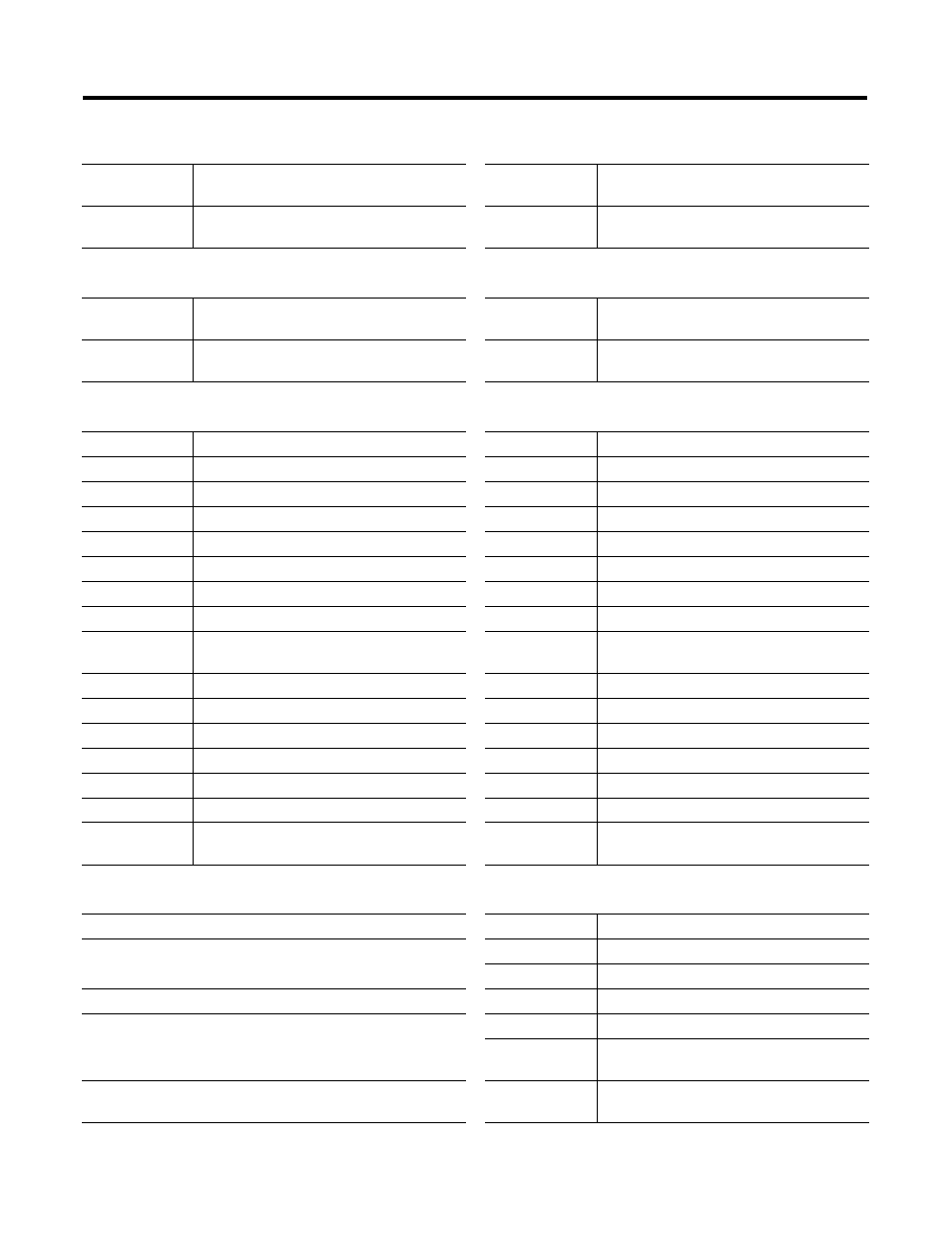
B-2 Input/Output Quick Reference
Bit 5
determines the active level of the home
proximity limit switch input
Bit 5
reflects active level of the home prox limit
switch input configured
Bits 6 through
15
not used
Bits 6 through
15
not used
CONFIG OUTPUT WORDS 2 and 3
CONFIG INPUT WORDS 2 and 3
Word 2
starting speed most significant word (MSW)
Word 2
reflects the starting speed most significant
word as configured in output word 2
Word 3
starting speed least significant word (LSW)
Word 3
reflects the starting speed least significant
word as configured in output word 3
COMMAND OUTPUT WORD 0
COMMAND INPUT WORD 0
Bit 0
absolute move
Bit 0
set when the axis is moving CW
Bit 1
relative move
Bit 1
set when the axis is moving CCW
Bit 2
hold motion
Bit 2
set when the module is in a hold
Bit 3
resume motion
Bit 3
set when the axis is stopped
Bit 4
immediate stop
Bit 4
set when the axis is in home position
Bit 5
find home
+
Bit 5
set when the axis is accelerating
Bit 6
find home –
Bit 6
set when the axis is decelerating
Bit 7
jog
+
Bit 7
set when the current move is complete
Bit 8
jog –
Bit 8
set when the module is in a blend move
mode
Bit 9
preset position
Bit 9
send next blend move data bit
Bit 10
reset errors
Bit 10
reset if position is valid
Bit 11
program blend move profile
Bit 11
set when input errors exist
Bit 12
read blend move profile
Bit 12
set when a command error exists
Bit 13
run blend move profile
Bit 13
set when a config error exists
Bit 14
preset encoder portion
Bit 14
set when the module is OK
Bit 15
mode flag:0
= command
1
= config
Bit 15
mode flag:0
= command
1
= config
COMMAND OUTPUT WORD 1
COMMAND INPUT WORD 1
reserved
Bit 0
set when CW limit switch is active
COMMAND OUTPUT WORD 2
Bit 1
set when CCW limit switch is active
Bit 2
set when immediate stop input is active
Position MSW 0 – 8338
Bit 3
set when external interrupt is active
COMMAND OUTPUT WORD 3
Bit 4
set when home limit switch is active
Bit 5
set when home proximity limit switch is
active
Position LSW 0 – 999
Bits 6 through
15
not used
CONFIG OUTPUT WORD 1
CONFIG INPUT WORD 1