Encoder feedback connections – Rockwell Automation 1746-HSTP1 Stepper Controller Module/ User Manual User Manual
Page 25
Publication 999-121 - December 1999
2-8 Installation and Wiring
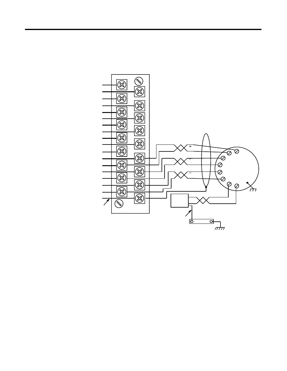
Encoder Feedback
Connections
The following two diagrams illustrate encoder connections to the
Module inputs for both 5-volt and 15-volt encoder power supplies.
The -notes" included with each diagram provide specifics on wiring.
Figure 2.7 5-volt encoder feedback connections
Notes:
1. Use 3-pair, #22 gauge individually twisted and shielded pair,
Belden 9504 or equivalent.
2. Use 1-pair, #18 gauge twisted and shielded cable.
3. Encoders must have
+5V compatible differential line drive
outputs on channels A, B, and Z. (DS8830, or equivalent.) (A-B
845H)
4.
+5V from encoder power source – connect encoder return to 0V
user power (DC common) at the power supply sources.
A
7-24V DC user power (1)
CW + or non directional pulse output (2)
CW - or non directional pulse output (3)
CW + pulse or direction signal output (4)
CCW - pulse or direction signal output (5)
External interrupt input (6)
Home limit switch input (7)
Home Proximity limit switch input (8)
CW limit switch input (9)
CCW limit switch input (10)
Pulse train enable/disable input (11)
A Hi (Loopback + non directional pulse) (12)
A Lo (Loopback - non directional pulse) (13)
B Hi (Loopback + direction) (14)
B Lo (Loopback - direction (15)
+ Encoder Marker (16)
- Encoder Marker (17)
0 V user power (DC common) (18)
1
1
1
+5V
Return
A
B
Z
A
H
B
I
C
J
D
F
G
Case Ground
A-B 845H
Optical
Encoder
3
DC
SOURCE
Z
B
Electrical Cabinet
Ground Bus
16 AWG
16 AWG