Establish a data echo, Slc output file to the interface module – Rockwell Automation 1747-KE,D17476.12 DH-485/RS-232C Interface Module User Manual
Page 83
Publication 1747-UM005B-EN-P - March 2006
Module Configuration Using the Backplane 6-17
Establish a Data Echo
Between the Interface
Module and the SLC
Processor
Whether in software Run or software Configuration mode, the SLC
processor can send data in the Output Image file to the interface
module and have it echoed back by the module’s Input Image file.
This feature gives the SLC processor the ability to verify that the
module is operating properly. If the data is not echoed back, the
module is assumed to be operating incorrectly and is forced into a
reset by the SLC processor.
See the section Resetting the Interface Module from the SLC processor.
Establish a Data Echo
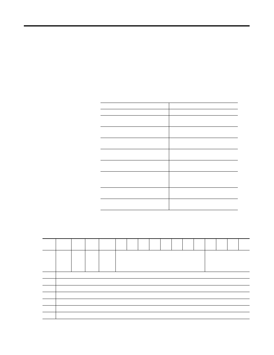
The SLC processor can set up the Data Echo configuration by building
the configuration packet shown below.
SLC Output File to the Interface Module
With the SLC processor you
The interface module then
1. Set the Data ID to 6 (O:e.0/0...3).
2. Load known data into words 1...7
of the output file (O:e.1...7).
3. Set the Data Handshaking bit
(O:e.0/14).
4. Verifies that the DF1 and DH-485
ports are okay.
5. Loads the data from the output
file into the input file.
6. Sets the Data Handshaking Bit
(I:e.0/14).
7. Verify that the Input File words
1...7 (I:e.1...7) match the Output
File (O:e.1...7).
8. Reset the Data Handshaking Bit
(O:e.0/14).
9. Resets the Data Handshaking Bit
(I:e.0/14).
Bit
Word
15
14
13
12
11
10
9
8
7
6
5
4
3
2
1
0
0
(1)
Module
Mode
Bit
Data
Hand
shake
Bit
Read
or
Write
Bit
Reset
Interface
Module
Bit
Reserved
Data ID=6
1
User-defined Data
2
User-defined Data
3
User-defined Data
4
User-defined Data
5
User-defined Data
6
User-defined Data
7
User-defined Data
(1)
The output status word is defined on page 6-6. To write the echo data packet, the Read or Write bit must be 0 and the Module Mode Bit can be either 0 or 1.