Overview of the data transfer scheme – Rockwell Automation 1771-SPI,D17716.5.122 SPI PROTOCOL INTERFACE User Manual
Page 9
Overview of an SPI Communication Network
Chapter 1
1-3
When you program the processor to communicate with devices on the SPI
network via the SPI module, you must follow a strict procedure of data
transfers that:
receives status from the SPI module
configures the SPI module with module-specific configuration (MCC)
configures the SPI module with device-specific configuration (CCB)
receives configuration status from the SPI module (SYS and CCS)
sends commands to the SPI module destined for target devices (CDB)
receives status from target devices via the SPI module (CDS)
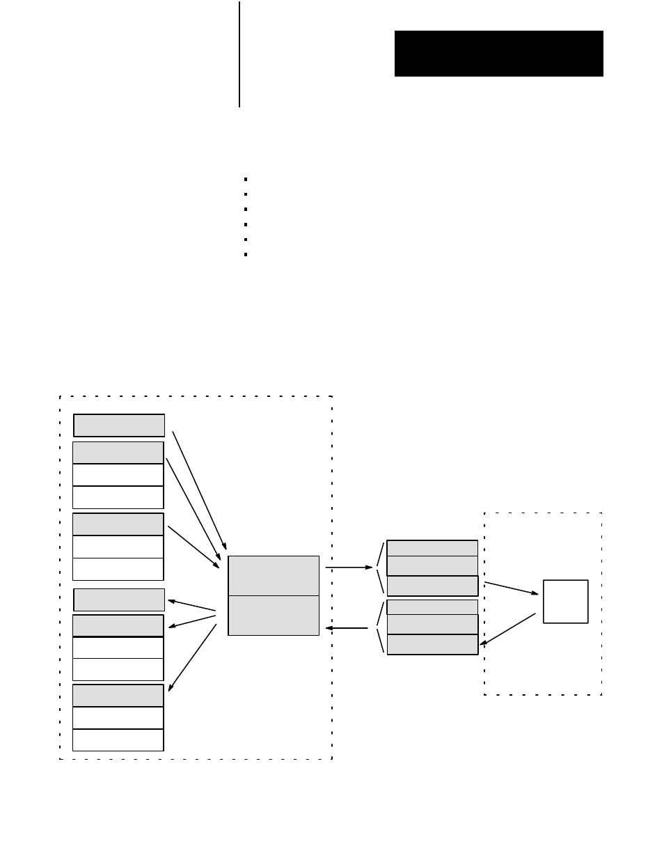
We show the general flow of configuration and command data transferred to
the SPI module, and status received from it. Once configured, the SPI
module serves as the master interface with slave devices on the link: the
module parces commands to target devices and polls status from them.
Transferring Configuration and Command Data
to One of Three Devices on an SPI Network
Data Table
Config CCB ID#20
Config CCB ID#21
Config CCB ID#22
Status CCS ID#20
Status CCS ID#21
Status CCS ID#22
BTW Buffer
BTR Buffer
Config CCB ID#20
SYS
SPI Module
Data CDB ID#20
Data CDB ID#21
Data CCB ID#22
Status CDS ID#20
Status CDS ID#21
Status CDS ID#22
MCC
SYS
Status CCS ID#20
Data CDB ID#20
MCC
Device
ID#20
Parces
Commands
Polls
Status
Status CDS ID#20
SPI Link
Overview of the Data
Transfer Scheme