Chapter 1 – Rockwell Automation 1771-SPI,D17716.5.122 SPI PROTOCOL INTERFACE User Manual
Page 10
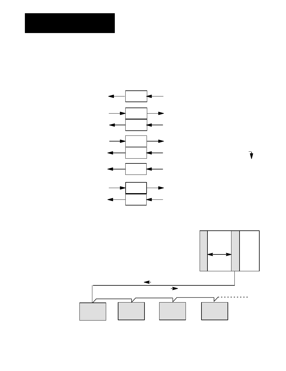
Overview of an SPI Communication Network
Chapter 1
1-4
You must program block transfer instructions according to an exact protocol.
Programming the Transfer of Configuration, Command, and Status Data
Programming That You Develop
Data Blocks Transferred
Automatic Response of SPI Module
Until your ladder logic tranafers a valid MCC to
the SPI module, it can only return SYS status
in response to a BTR request.
To set the SPI module into operation,
send (BTW) a valid MCC to it.
Your ladder logic moves the CCS into the data
table where your program checks its validity.
To configure the SPI for a custom device type,
move deviceĆspecific custom configuration (CCB)
to the BTW buffer for transfer to the SPI module.
The SPI module returns the current SYS status
to the processor.
After storing a valid MCC, the SPI module sets the
powerĆup bit in SYS and returns SYS to the processor.
Now it is ready for custom configuration.
SYS
BTR
BTW
MCC
SYS
CCS
CCB
BTR
BTR
BTW
The SPI module formats and stores the CCB. Then it
returns the corresponding CCS to acknowledge receipt
of the CCB. Store a CCB for each type of device.
Your ladder logic moves SYS from the
BTR buffer into the data table.
Your ladder logic moves the CDS into the data
table for use in your application program.
To communicate with target custom devices,
move deviceĆspecific data (CDBs) to the BTW
buffer for transfer to the SPI module.
The SPI module returns status (CDS) to the processor
each time it sends a CDB to a target device.
CDS
CDB
BTR
BTW
The SPI module formats and stores CDBs. Then it
interrupts automatic polling and sends data to target
devices in queue order.
CDS
BTR
After storing CCBs, the SPI module begins automatic
polling: it reads status from the first device and returns
CDS to the processor. Then repeats for each device
on the network in queued order as listed in the MCC.
Your ladder logic moves CDS into the data table
for use in your application program.
Mold
Temperature
Controller
10579-2
Block
Transfers
Hot
Runner
Controller
Dryer
Controller
Loader
Controller
PLC-5 Controller
SPI Interface Module
1771 I/O Chassis
You program the PLCĆ5 processor to:
* set the size and contents of command and status data blocks
* block transfer command and status data between PLCĆ5 processor and SPI module
* specify the queue order in which the SPI module communicates with its devices
When commanded, the SPI module:
* communicates serially with each device on the SPI network in queued order
* sends programmed command data such as setpoints and alarm values to each device
* receives status data such as alarm bits and stored values from each device
* returns status data to the processor when it receives a BTR instruction
When polled in queued order, each device on the SPI network:
* stores command bits, setpoints, and alarm values received from the SPI module
* returns alarm bits and requested status to the SPI module
command data
status data