Scaling – Rockwell Automation 1756-IF4FXOF2F ControlLogix High-speed Analog I/O Module User Manual
Page 36
36
Rockwell Automation Publication 1756-UM005B-EN-P - January 2013
Chapter 3
Module Features
Use
Table 3
to see the resolution for each module range.
Scaling
The scaling feature provides the option to change a quantity from one notation to
another. When you scale a channel, you must choose two points along the
channel’s operating range and apply low and high values to those points.
For example, if you use an input in Current mode, the channel maintains a
0…21mA range capability. But your application may use a 4…20 mA transmitter.
You can scale the module to represent 4 mA as the low signal and 20 mA as the
high signal and scale that into engineering units of your choice.
In this case, scaling can cause the module to return data to the controller so that
4 mA returns a value of 0% in engineering units and 20 mA returns a value of
100% in engineering units.
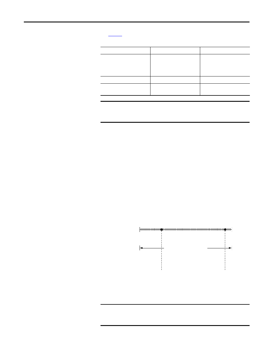
Figure 5 -
Module Resolution Compared to Module Scaling
Table 3 - Module Resolution Range
Input Range
Effective Bits across Range
Resolution
±10V
0V…10V
0V…5V
0 mA…21 mA
14 bits
13 bits
12 bits
12 bits
1.3 mV/count
1.3 mV/count
1.3 mV/count
5.25
μ
A/count
Output Range
Effective Bits across Range
Resolution
±10V
0 mA…21 mA
14 bits
13 bits
1.3mV/count
2.8
μ
A/count
IMPORTANT
Because this module must allow for possible calibration inaccuracies,
resolution values represent the available analog-to-digital or digital-to-analog
counts over the specified range.
IMPORTANT
In choosing two points for the low and high value of your application, you do
not limit the range of the module. The module’s range and its resolution
remain constant regardless of how you scale it for your application.
Module Resolution
4096 Counts
0 mA
21 mA
4 mA
20 mA
0% in Engineering Units
100% in Engineering Units
Module Scaling
Module scaling represents the data returned from the module to the controller.