E scaling select (bits 13-14), Scaling select (bits 13-14) – Rockwell Automation 1746-NR4 SLC RTD/Resistance Input Module User Manual User Manual
Page 78
Publication 1746-UM008B-EN-P - December 2006
78 Channel Configuration, Data, and Status
Scaling Select (Bits 13-14)
If you selected proportional counts as the format for your input data,
you can enter a scaling range that ensures your data is scaled within a
range appropriate for your use. You can use words 4 and 5 to define
one range and words 6 and 7 to define a second range. The Bit
Descriptions for Scaling Selection table gives the descriptions for bits
13 and 14.
Default Scaling
The first case to consider is when default scaling is selected and the
scaling select bits (bits 13 and 14) are set to 00 (module defined
scaling).
Refer to Scaled–for–PID on page 68 and Proportional Counts Data
Format on page 69 for considerations when using default values.
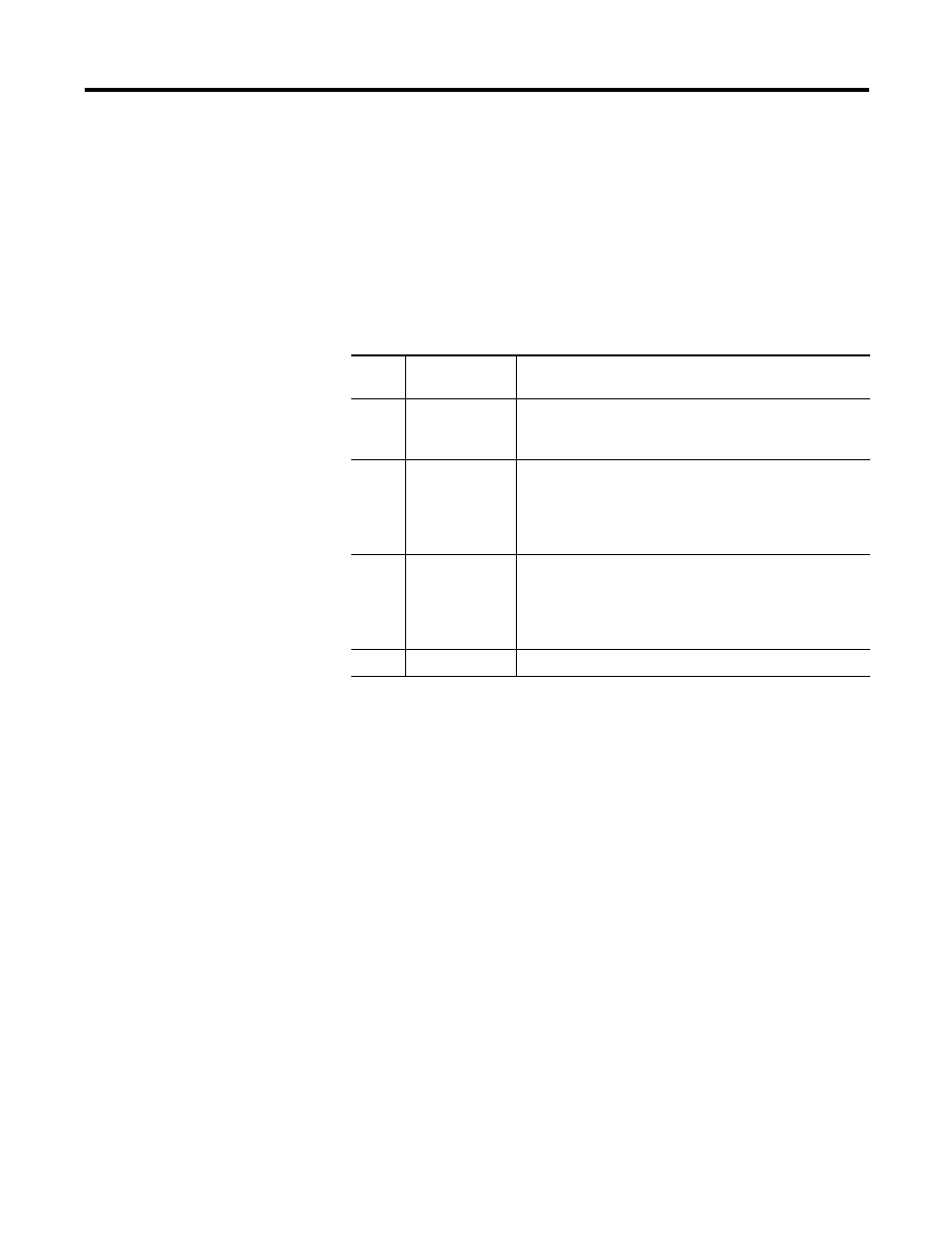
Bit Descriptions for Scaling Selection
Binary
Value
Select
If you want to
00
Use module
defined scaling
Configure the module to scale the data word using the
default scale range (-32,768 to 32,767) for scaled-for-PID and
proportional counts.
01
Use
configuration
words 4 and 5 for
scaling (range 0)
Define a range (range 0) that your proportional counts data
will be scaled to. Configuration word 4 contains the low
scale limit and configuration word 5 contains the high scale
limit. If you make this setting, be sure to enter low and high
scale values into configuration words 4 and 5.
10
Use
configuration
words 6 and 7 for
scaling (range 1)
Define a range (range 1) that your proportional counts data
will be scaled to. Configuration word 6 contains the low
scale limit and configuration 7 contains the high scale limit.
If you make this setting be sure to enter low and high scale
values into configuration words 6 and 7.
11
not used
(configuration error)