Channel filter frequency selection, Channel step response – Rockwell Automation 1746-NR4 SLC RTD/Resistance Input Module User Manual User Manual
Page 54
Publication 1746-UM008B-EN-P - December 2006
54 Preliminary Operating Considerations
Chapter 5, Channel Configuration, Data, and Status, gives you detailed
bit information about the content of the data word and the status
word.
The RTD module uses a digital filter that provides noise rejection for
the input signals. The digital filter is programmable, allowing you to
select from four filter frequencies for each channel. The digital filter
provides the highest noise rejection at the selected filter frequency.
Channel Filter Frequency
Selection
Selecting a low value (for example, 10 Hz) for the channel filter
frequency provides greater noise rejection for a channel, but also
increases the channel update time. Selecting a high value for the
channel filter frequency provides lesser noise rejection, but decreases
the channel update time.
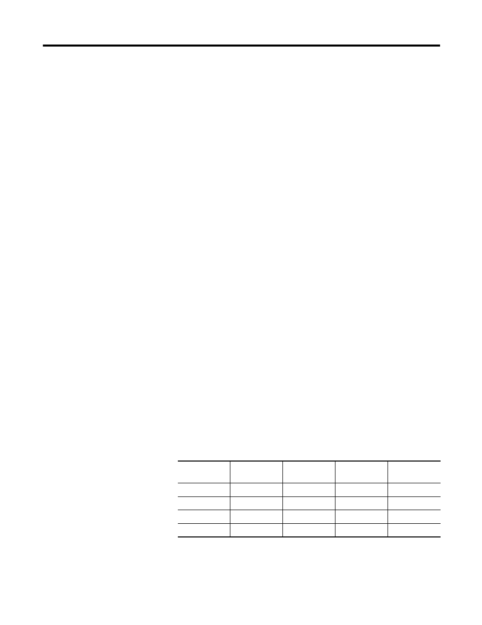
The Notch Frequencies table shows the available filter frequencies, as
well as the associated minimum normal mode rejection (NMR), cut-off
frequency, and step response for each filter frequency.
The figures on pages 56 and 57 show the input channel frequency
response for each filter frequency selection.
Channel Step Response
The channel filter frequency determines the channel’s step response.
The step response is the time required for the analog input signal to
reach 100% of its expected final value. This means that if an input
signal changes faster than the channel step response, a portion of that
signal will be attenuated by the channel filter. The table below shows
the step response for each filter frequency.
Notch Frequencies
Filter
Frequency
50 Hz NMR
60 Hz NMR
Cut-off
Frequency
Step
Response
10 Hz
100 dB
100 dB
2.62 Hz
300 ms
50 Hz
100 dB
-
13.1 Hz
60 ms
60 Hz
-
100 dB
15.72 Hz
50 ms
250 Hz
-
-
65.5 Hz
12 ms