Rockwell Automation 1746-NR4 SLC RTD/Resistance Input Module User Manual User Manual
Page 101
Publication 1746-UM008B-EN-P - December 2006
Module Diagnostics and Troubleshooting 101
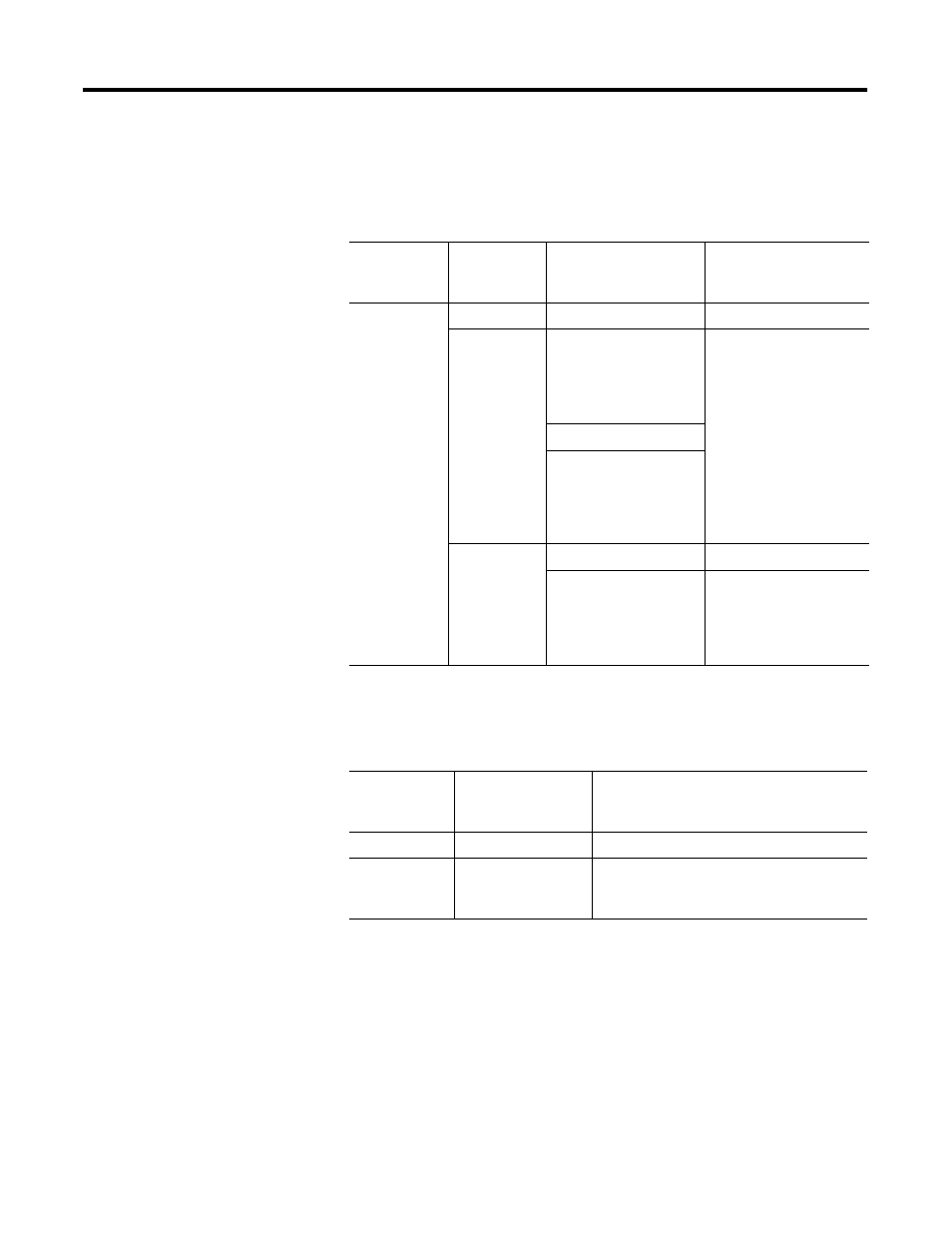
The LED Indicator Status Description table explains the function of the
channel status LED indicators while the module status LED indicator is
turned on.
The Module Status LED Indicator State table explains the function of
the module status LED indicator.
I/O error codes are reported in word S:6 of the SLC processor status
file. The characters denoted as XX represent the slot number (Hex) for
the module. The characters denoted as YY represent the 2-digit hex
code for the fault condition.
The format for the error codes in the status word (S:6) is shown in the
Error Code Format diagram on page 102.
LED Indicator Status Description
If Module
Status LED
Indicator is
And Channel
Status LED
Indicator is
Indicated Condition
Corrective Action
On
On
Channel enabled
No action required.
Flashing
Broken Input Condition
(open circuit for RTD or
resistance input, and
short circuit for RTD
inputs only)
To determine the exact
error, check the error bits
13…15 in the input image.
Check the channel
configuration word for
valid data. Make sure that
the input type is indicated
correctly in bits 0…3.
Refer to the
troubleshooting flowchart
on page 7-6 and chapter 5
for more information.
Out-of-range Condition
Channel Configuration
Error
Off
Power-Up
No action required.
Channel Not Enabled
No action required. For an
example of how to enable
a channel refer to chapter
6, Ladder Programming
Examples.
Module Status LED Indicator State
If Module
Status LED
Indicator is
Indicated Condition Corrective Action
On
Proper Operation
No action required.
Off
Module Fault
Cycle power. If condition persists, replace the
model or call your local distributor or
Allen-Bradley for assistance.