Rockwell Automation 1746-NR4 SLC RTD/Resistance Input Module User Manual User Manual
Page 20
Publication 1746-UM008B-EN-P - December 2006
20 Overview
The A/D convertors cycle between reading the RTD or resistance
value, the lead wire resistance, and the excitation current. From these
readings, an accurate temperature or resistance is returned to the user
program.
The RTD module is isolated from the chassis backplane and chassis
ground. The isolation is limited to 500V dc. Optocouplers are used to
communicate across the isolation barrier. Channel-to-channel
common-mode isolation is limited to X 1 volt.
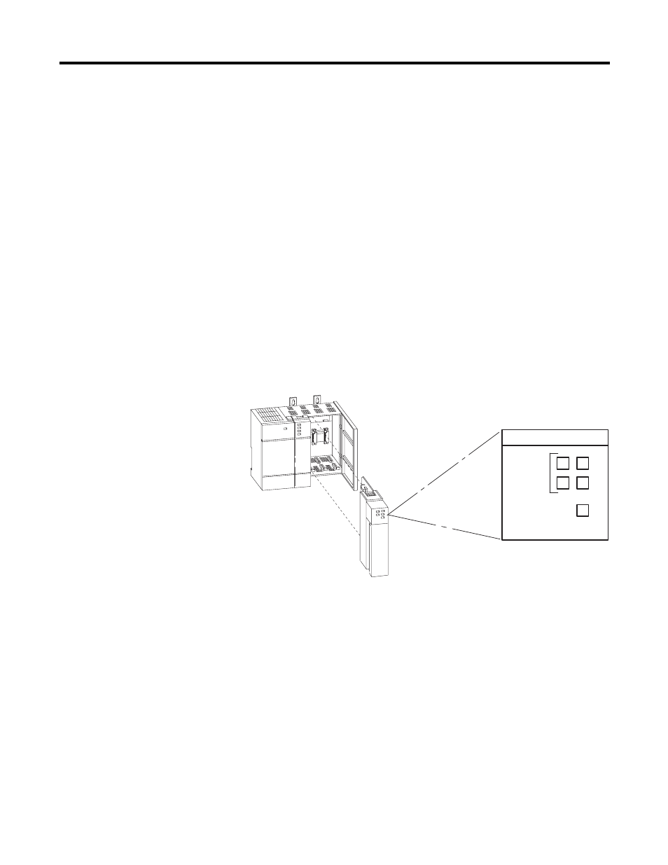
LED Indicator Status
The following figure shows the RTD module LED indicator panel
consisting of five LED indicators. The state of the LED indicators (for
example, off, on, or blinking) depends on the operational state of the
module.
See the LED Indicator Status table on page 21.
LED Indicators
The purpose of the LED indicators is to provide:
• Channel Status - One LED indicator for each of the four input
channels indicates if the channel is enabled, disabled, or is not
operating as configured, due to an error.
• Module Status - If OFF at any time, other than when you cycle
module power, this LED indicator indicates that non-recoverable
module errors (for example, diagnostic or operating errors) have
occurred. The LED indicator is ON if there are no module errors.
MODULE STATUS
INPUT
0
2
1
3
CHANNEL
STATUS
RTD/resistance